Positive Drive for a Spiral Conveyor and Belt Module for a Radius or Spiral Conveyor

a technology of spiral conveyor and belt module, which is applied in the direction of conveyors, packaging, transportation and packaging, etc., can solve the problems of difficult to predict the coefficient of friction between the drum and the belt, the coefficient of friction, and the drive edge wear of the conveyor belt and the outer surface of the drum, so as to increase the collapse of the collapsible tabs, increase the belt tension, and increase the belt tension

Active Publication Date: 2019-01-17
HABASIT AG
View PDF3 Cites 9 Cited by
  • Summary
  • Abstract
  • Description
  • Claims
  • Application Information

AI Technical Summary

Benefits of technology

[0010]In some embodiments of spiral conveyor, each drive bar has a width selected to act on a predetermined number of unengaged collapsible tabs of rows. A radius of the conveyor belt along the helical path may decrease as the unengaged collapsible tabs are urged against the drive bars by increasing belt tension. The drum may further include a guide at the infeed, where the guide is configured to ease the conveyor belt into engagement with the drive bars of the drum. The guide may be configured to ease the conveyor belt into engagement with the drive bars over a distance of, for example, between 0.1 and 3 meters, inclusive, but could be greater or less. The guide may be, for example, a rail. Each row of belt modules may include a tooth configured to act on the rail. In some embodiments, the guide is a tapered skirt interdigitated with the drive bars.
[0011]In another aspect, the present disclosure may be embodied as a method for load compensation in a radius belt. The method includes providing a belt having a plurality of belt modules each with a collapsible tab at a first transverse end of the respective belt module. For example, the belt may be configured as any belt with collapsible tabs described herein. During belt travel around a radius turn, the collapsible tabs of a subset of the plurality of belt modules are contacted with a frame member at an insider (inner side) of the radius turn. The collapsible tabs are caused to collapse against the frame member according to a tension of the belt. A higher belt tension will cause an increased collapse of the collapsible tabs thereby reducing a radius of the belt at the radius turn. A lower belt tension will cause a decreased collapse of the collapsible tabs thereby increasing a radius of the belt at the radius turn. The frame member may further comprise a plurality of drive bars. In some embodiments, the frame member is stationary.

Problems solved by technology

However, overdrive systems for spiral conveyors may create considerable wear on the driven edge of the conveyor belt and the outer surfaces of the drum due to the constant slipping of the belt on the drum.
Additionally, it is difficult to predict the coefficient of friction between the drum and the belt because the coefficient depends on factors such as temperature, humidity, surface roughness, surface shape, contact pressure, speed, etc.
Another impact to the coefficient of friction results from the articles being conveyed.
Ultimately, such a change in driving force will likely interrupt production due to belt lift up, belt breakage, or both.
However, positive drive systems are problematic where the conveyor belt comes into contact with the drum (the “infeed”).
This difference in pitch can cause chatter, surges in belt tension, and other issues with the conveyor belt which can result in belt breakage.

Method used


Image

  • Positive Drive for a Spiral Conveyor and Belt Module for a Radius or Spiral Conveyor
  • Positive Drive for a Spiral Conveyor and Belt Module for a Radius or Spiral Conveyor
  • Positive Drive for a Spiral Conveyor and Belt Module for a Radius or Spiral Conveyor

Examples


Embodiment Construction

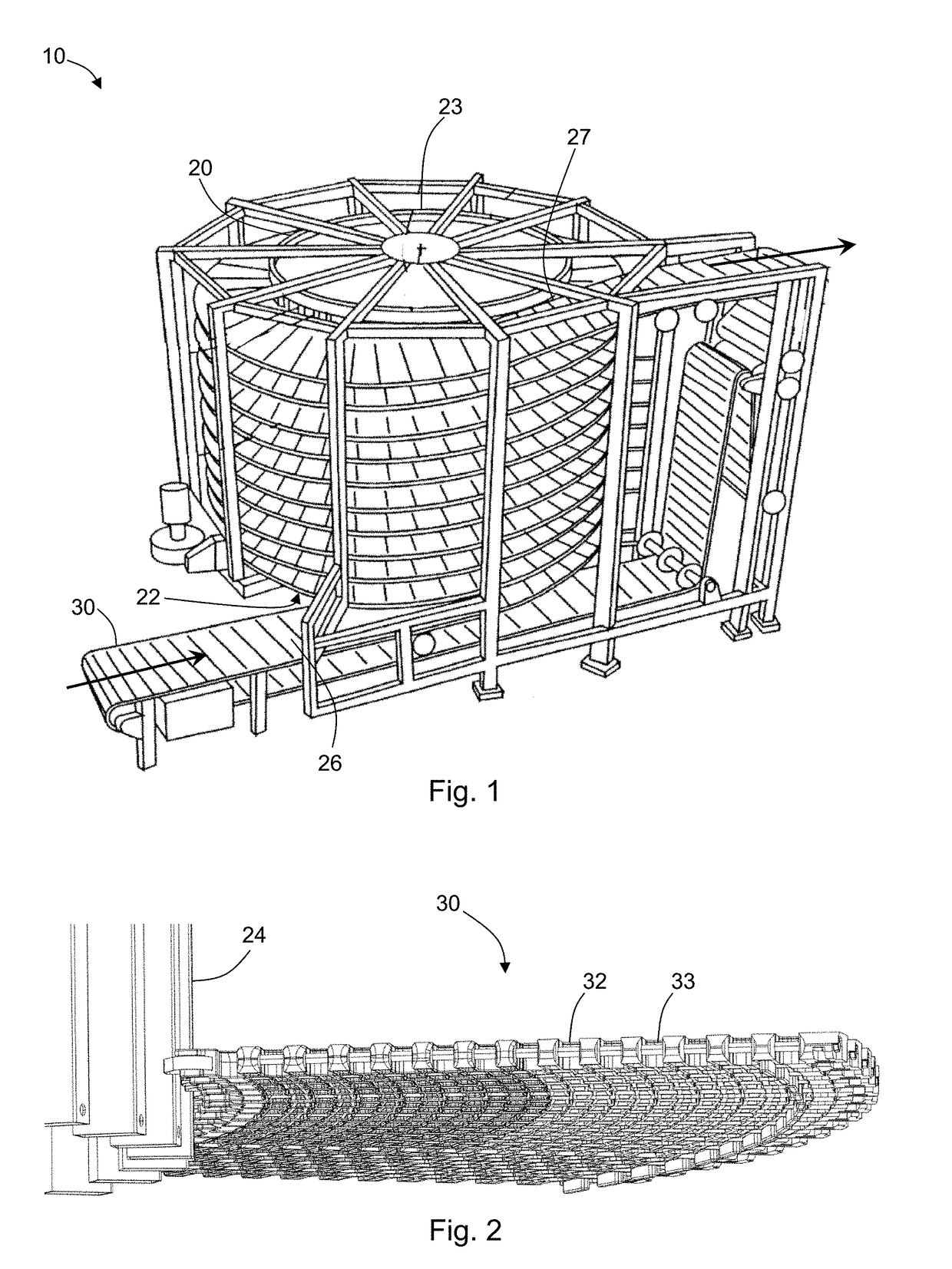
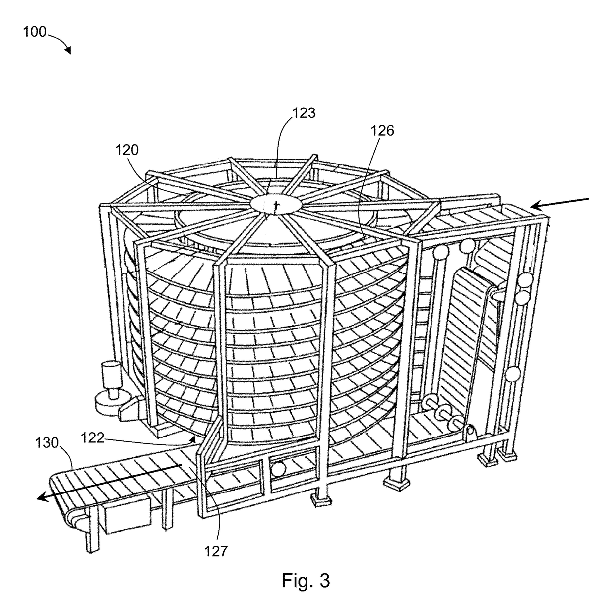
[0034]With reference to FIG. 1, the present disclosure may be embodied as a spiral conveyor 10. The spiral conveyor 10 has a rotating drum 20 with a cylindrical periphery extending from a bottom end 22 of the drum 20 to a top end 23 of the drum 20. A plurality of drive bars 24 are arranged on the periphery of the drum 20 (see, e.g., FIG. 2). The drive bars 24 are arranged parallel with one another. In some embodiments, the drive bars 24 are arranged such that a primary longitudinal axis of each drive bar 24 is perpendicular to a direction of drum rotation (i.e., parallel to the rotational axis of the drum 20).

[0035]The spiral conveyor 10 has a conveyor belt 30 which is configured to advance along a helical path around the periphery of the drum 20 from an infeed 26 (where the belt 30 first engages the drum 20) to an outfeed 27 (where the belt 30 disengages the drum 20). In some embodiments, the infeed 26 may be near the bottom end 22 of the drum 20 and the outfeed 27 is near the top ...


PUM


Abstract

The present disclosure may be embodied as a belt module for a radius or spiral conveyor. The belt module includes first link ends extending in a direction of belt travel. Each first link end has a transverse opening. Second link ends extend in a direction opposite the first link ends and are configured to interdigitate with the first link ends of an adjacent belt module, and each second link end has a transverse opening defined therein. The transverse openings of the first and/or the second link ends are elongated. The belt modules further include a collapsible tab for contacting a frame member. The collapsible tab is located at a first transverse end of the belt module. In some embodiments, the collapsible tab is configured to engage a drive bar. The belt module may further include a guide tooth on a bottom side of the module for engaging a guide.

Description

FIELD OF THE DISCLOSURE[0001]The present disclosure relates to spiral conveyors, and more particularly to drive systems used for spiral conveyors.BACKGROUND OF THE DISCLOSURE[0002]Conveyor belts traveling a helical path (so-called “spiral conveyors”) are often used to convey articles through climate-controlled environments over an extended period of time. For example, spiral conveyors are used to convey food items through freezers, proofers, etc.[0003]Some previous spiral conveyors have been driven at locations of the belt path outside the spiral, requiring a very high belt tension near the drive location(s) in order to pull the belt through the spiral. To reduce the belt tension, other spiral conveyors have been driven using an overdrive configuration where a conveyor belt follows a helical path around a central drum, and the central drum drives the belt by friction with the inside edge of the belt. The central drum is driven at a speed which is greater than the speed of the belt (...

Claims


Application Information

Patent Timeline
Patent Type & Authority Applications(United States)
IPC IPC(8): B65G17/08B65G17/38B65G17/40B65G21/18B65G23/06B65G23/44
CPCB65G17/086B65G17/385B65G17/40B65G21/18B65G23/06B65G23/44B65G2207/24
Inventor ELSNER, DIETMARMORITZ, MARTINTHUET, ARNAUD
Owner HABASIT AG
Why Eureka
Try Eureka