

Apparatus and Method to Render Air Bag Inflators and Other Low Level Detonatable Devices Inert for Recycling
- Summary
- Abstract
- Description
- Claims
- Application Information
AI Technical Summary
Benefits of technology
Problems solved by technology
Method used
Image

Examples
Embodiment Construction
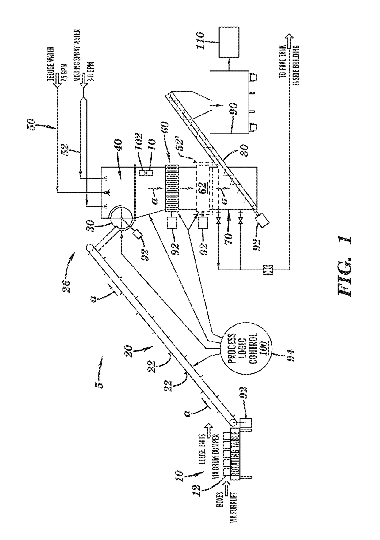
[0014]It should be understood at the outset that, although exemplary embodiments are illustrated in the FIGURE and described below, the principles of the present disclosure may be implemented using any number of techniques, whether currently known or not. The present disclosure should in no way be limited to the exemplary implementations and techniques illustrated in the drawings and described below. Additionally, unless otherwise specifically noted, articles depicted in the drawings are not necessarily drawn to scale. In addition, well-known structures, circuits and techniques have not been shown in detail in order not to obscure the understanding of this description. The following detailed description is, therefore, not to be taken in a limiting sense, and the scope of the present invention is defined by the appended claims and their equivalents.
General Overview
[0015]The present inventor has recognized that in order to recycle as scrap certain devices that may or may not be deemed...
PUM
 Abstract
Description
Claims
Application Information