

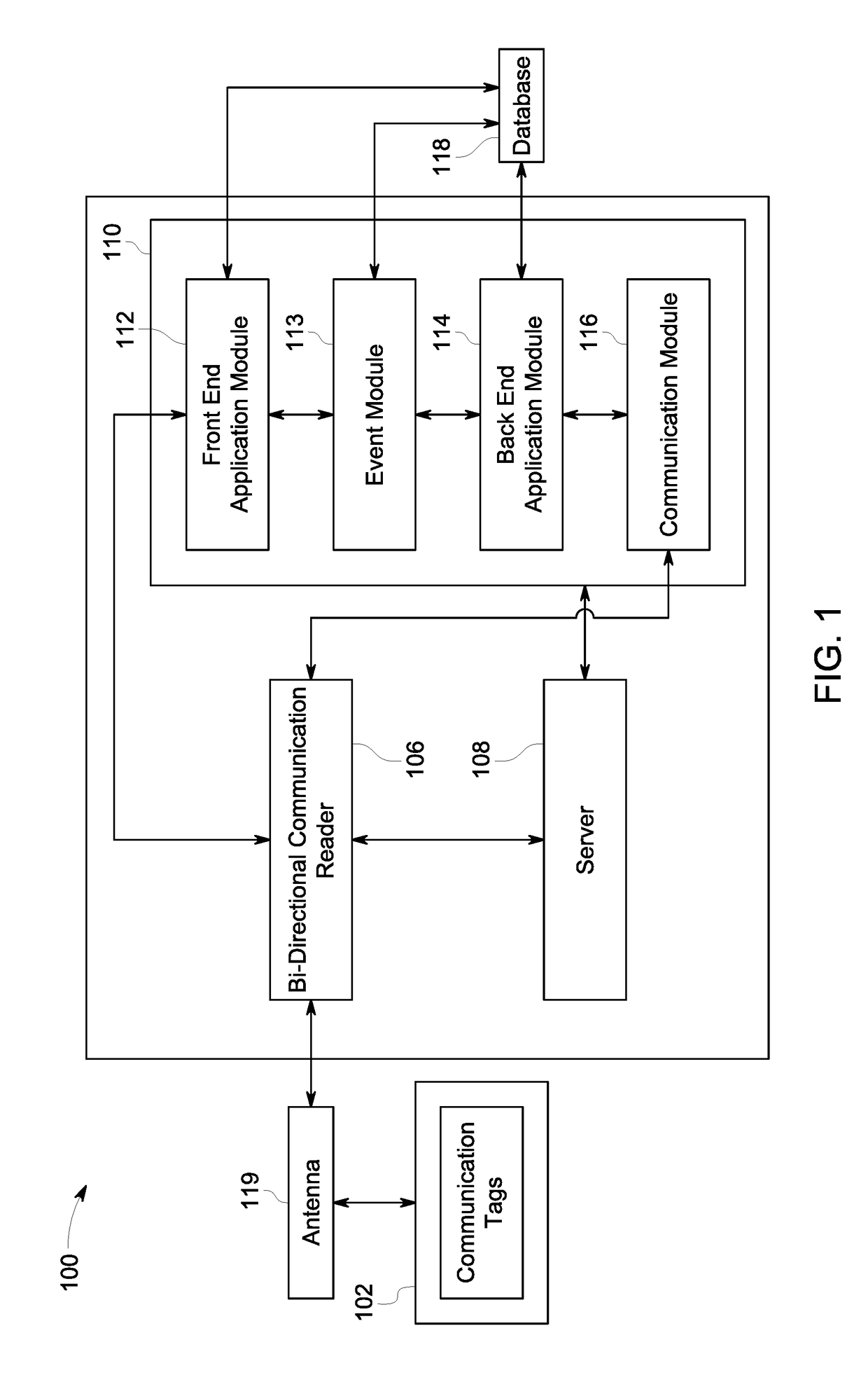
System and a method for detecting information of assets stored in communication tags
a technology of communication tags and information, applied in the field of system and method for detecting information of assets stored in communication tags, can solve problems such as current applications failing to provide a back end application
- Summary
- Abstract
- Description
- Claims
- Application Information
AI Technical Summary
Benefits of technology
Problems solved by technology
Method used
Image

Examples
example 1
—Finding Metal Parts
[0133]The present invention may be installed in an industrial workroom to allow users to find the location of metal parts, parts containers, and work orders, which accompany each part located in the workroom. Metal parts to track vary in size from a few inches to a few feet with smaller parts assigned in plastic bins. A work order accompanies each part or container.
[0134]In the warehouse, there may be 30 work zones to cover with each zone roughly 12 feet×12 feet in dimension. The configuration of desks or workspaces within each zone is not set as the furniture or workbenches may be set up differently depending on the project being worked on at the time.
[0135]Each asset may be tagged by an RFID UHF 18000-6C Gen2 tag specifically designed for the specific end-user. As configured and described herein, the present invention provides the user with location information of any asset within a zone in real time. The present invention may store the data information in the ...
example 2
Patient in a Hospital, Rehab Facility or Assisted Care Center
[0137]In this example, the goal is to develop a solution that informs the staff when patients access the hallways at any time during the day or night or leave a facility.
[0138]Each patient may be fitted with an ISO-18000-60 Gen 2 tag around their neck or other comparable location.
[0139]As configured and described herein, the present invention detects patients who access the hallway. The hallways may contain one or more antennas. The readers may be connected via a 24V output POE switch. The gateway may be installed in a control room or ceiling with a UPS emergency power supply. As the patient moves throughout the facility, the reader is configured to send the patient location in real time to the gateway.
[0140]The information stored may contain the location of each patient. The data stored may also contain the date and time of last detection for each patient in a designated area.
PUM
 Abstract
Description
Claims
Application Information