
Display device and smart mobile device

Inactive Publication Date: 2019-01-24
WUHAN CHINA STAR OPTOELECTRONICS TECH CO LTD
View PDF2 Cites 4 Cited by
  • Summary
  • Abstract
  • Description
  • Claims
  • Application Information

AI Technical Summary

Benefits of technology

The present invention relates to a display device and a smart mobile device. The invention configurations the position of the LED and the IC chip, which helps to solve the heat dissipation problem that affects the LED. As a result, the display device becomes more stable and has a longer lifespan.

Problems solved by technology

Due to the heat dissipation of the integrated circuit chip 50, such configuration may cause the backlight module malfunction.

Method used


Image

  • Display device and smart mobile device
  • Display device and smart mobile device

Examples


Embodiment Construction

[0019]Embodiments of the invention will now be described more fully hereinafter with reference to the accompanying drawings, in which embodiments of the invention are shown.

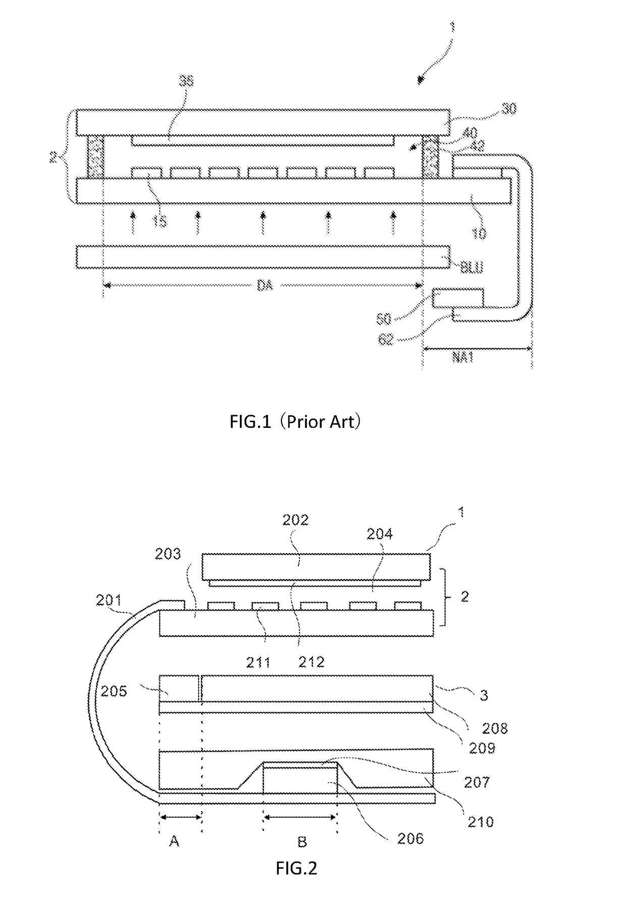
[0020]FIG. 2 is a schematic view of the display device in accordance with one embodiment of the present disclosure. The display device 1 includes a flexible circuit board 201, a display module 2, and a backlight module 3. The display module 2 includes a CF substrate 202, an array substrate 203, and a liquid crystal layer 204 between the CF substrate 202 and the array substrate 203.

[0021]In one embodiment, the backlight module 3 is an edge-type backlight module. The backlight module 3 includes at least one LED 205 arranged within a first area (A) of the display module, and the first area is perpendicular to the display module. The backlight module 3 further includes a light guiding plate 208 and a silver reflective film 209.

[0022]The CF substrate 202 includes a CF layer 212. The array substrate 203 includes at lea...


PUM


Abstract

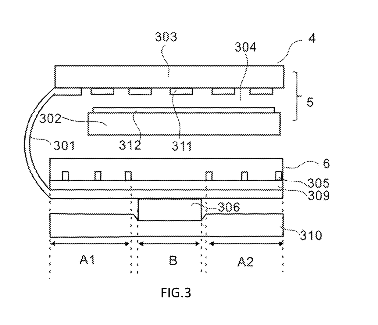
The present disclosure relates to a display device and a smart mobile device. The display device includes a flexible circuit board, a display module, and a backlight module. The display module includes a color filter (CF) substrate, an array substrate, and a liquid crystal layer between the CF substrate and the array substrate. The backlight module includes a plurality of LEDs arranged in a first area of the display module. A first end of the flexible circuit board is configured with electrical contact points electrically connecting to the array substrate, and a second end of the flexible circuit board is configured with an integrated circuit (IC) chip arranged in a second area of the display module. The first area and the second area are adjacent to each other, or the first area and the second area are spaced apart from each other.

Description

BACKGROUND OF THE INVENTION1. Field of the Invention[0001]The present disclosure relates to display technology, and more particularly to a display device and a smart mobile device.2. Discussion of the Related Art[0002]In recent years, narrow border technology has become one of the core technologies of various panel manufacturers. By optimizing the visual area on both sides of the non-visible area of the circuit arrangement and space ratio, the borders at two sides of the visible area are narrowed and thus have been recognized by the market.[0003]FIG. 1 is a cross sectional view of one conventional display device. The liquid crystal device (LCD) 1 includes a color filter (CF) substrate 30 having a CF layer 35; an array substrate 10 having a thin film transistor (TFT), gate lines, data lines, and the pixel electrode 15; a liquid crystal layer 40 between the CF substrate 10 and the array substrate 10. A plurality of gate welding electrodes and a plurality of data welding electrodes are...

Claims


Application Information

Patent Timeline
IPC IPC(8): G02F1/1345G02F1/1335G02F1/1368F21V8/00G02F1/1333
CPCG02F1/13452G02F1/133514G02F1/133603G02F1/133528G02F1/1368G02F1/133605G02B6/0055G02F1/133308G02B6/0085G02F2001/133317H05K1/147H05K2201/056H05K2201/10136G02F2001/133628G02F1/133615G02F1/1362G02F1/133562G02F1/133613G02F1/133317G02F1/133628
Inventor YANG, YONG
Owner WUHAN CHINA STAR OPTOELECTRONICS TECH CO LTD
Learn More