Plate member, casing including plate member and manufacturing method thereof

a technology of plate member and plate body, which is applied in the field of casing, can solve the problems of insufficient strength, and achieve the effect of reducing weight and improving mechanical strength

Inactive Publication Date: 2019-01-24
COMPAL ELECTRONICS INC
View PDF4 Cites 0 Cited by
  • Summary
  • Abstract
  • Description
  • Claims
  • Application Information

AI Technical Summary

Benefits of technology

[0004]The present invention provides a casing, which can improve the mechanical strength and achieve the effect of weight reduction.
[0005]The present invention provides a manufacturing method of a casing, which can produce a casing having the above advantages.
[0021]The casing of the embodiment of the invention includes a plate member and a resin member. The first surface layer of the plate member has a plurality of first through holes disposed on at least one edge of the first surface layer, so that when the filler is injected between the first surface layer and the second surface layer, it can be partially diverted to the plurality of first through holes to reduce the degree of compression of the core layer, and to reduce the weight of the plate member and the casing, thereby achieving an effect of weight reduction. In addition, the extension portion of the resin member formed by the cured filler, which is partially diverted into the plurality of first through holes, can also strengthen the bonding ability of the resin member and the first surface layer, thereby improving the mechanical strength of the casing. Since the manufacturing method of the casing of the embodiment of the invention uses the above-mentioned plate member, it is possible to produce a casing having the above advantages.

Problems solved by technology

The conventional notebook computer uses a plastic casing, and although the cost is inexpensive, it is obviously insufficient in strength after being thinned to reduce volume and weight.

Method used


Image

  • Plate member, casing including plate member and manufacturing method thereof
  • Plate member, casing including plate member and manufacturing method thereof
  • Plate member, casing including plate member and manufacturing method thereof

Examples


Embodiment Construction

[0029]In the following detailed description of the preferred embodiments, a range represented by “a value to another value” is a schematic representation that avoids listing all the values in the range in the specification. Therefore, the recitation of a particular range of values is equivalent to the disclosure of any value in the range of values and a smaller range of values defined by any value within the range of values, as if the arbitrary values and the smaller range of values are written in the specification. For example, the description of the range of “10 mm-100 mm” is equivalent to disclosing the range of “20 mm-50 mm”, regardless of whether other values are listed in the specification.

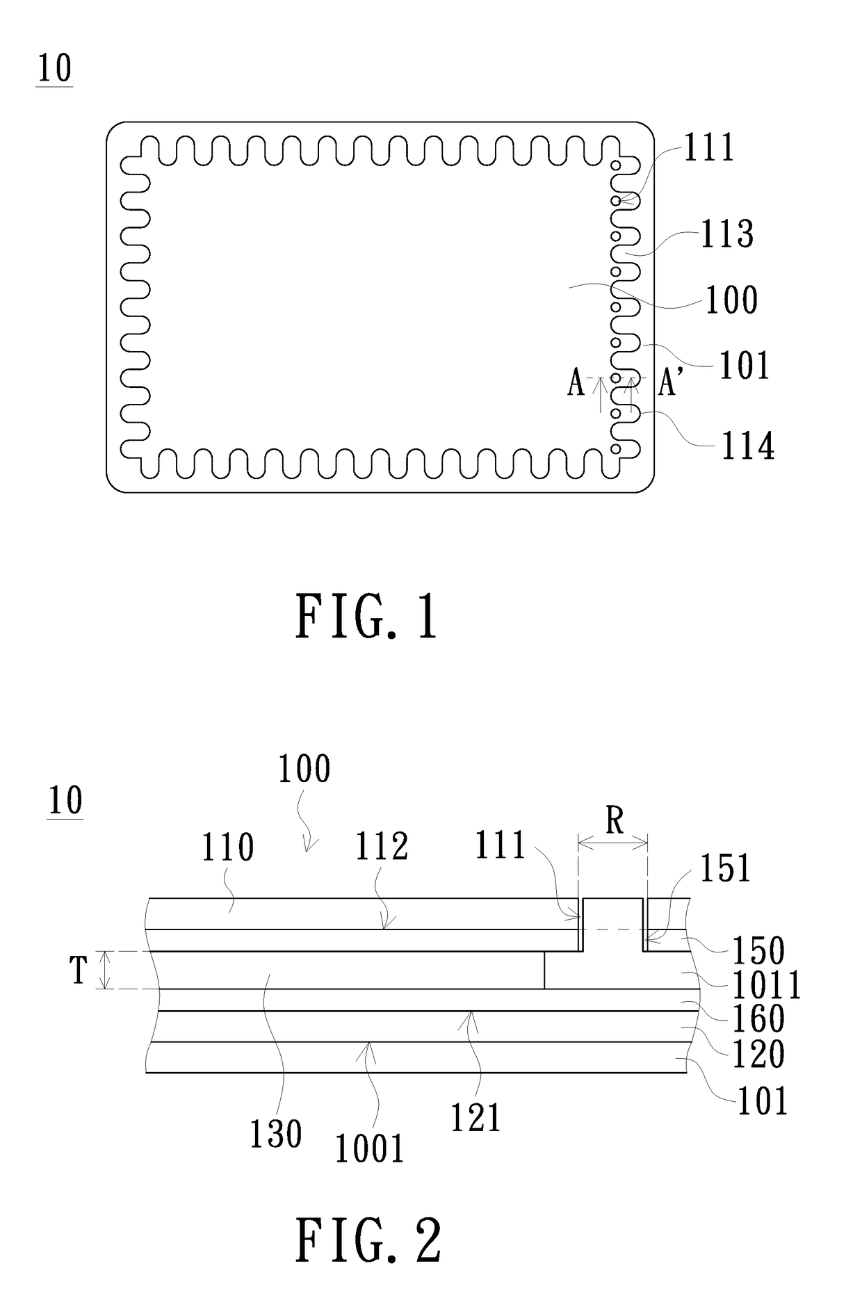
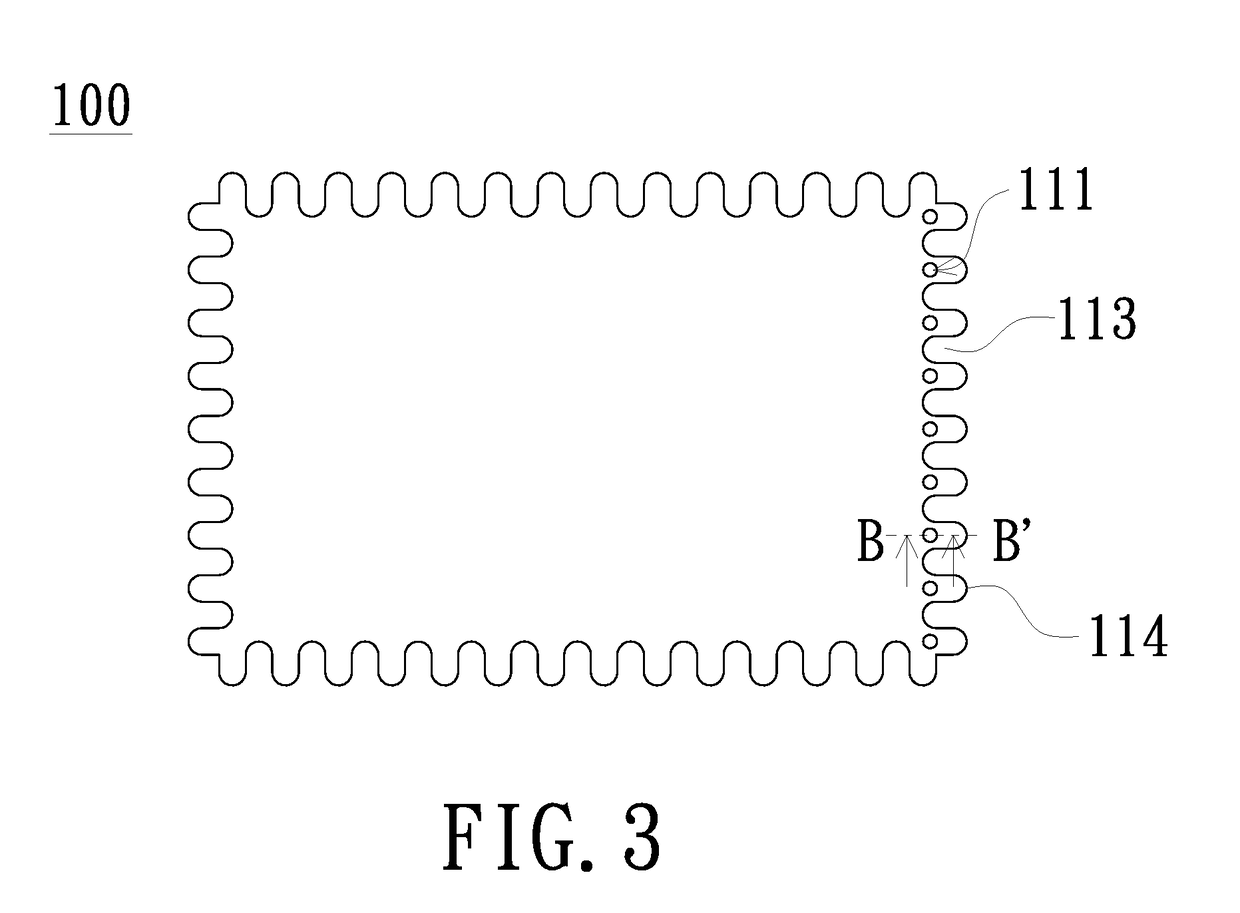
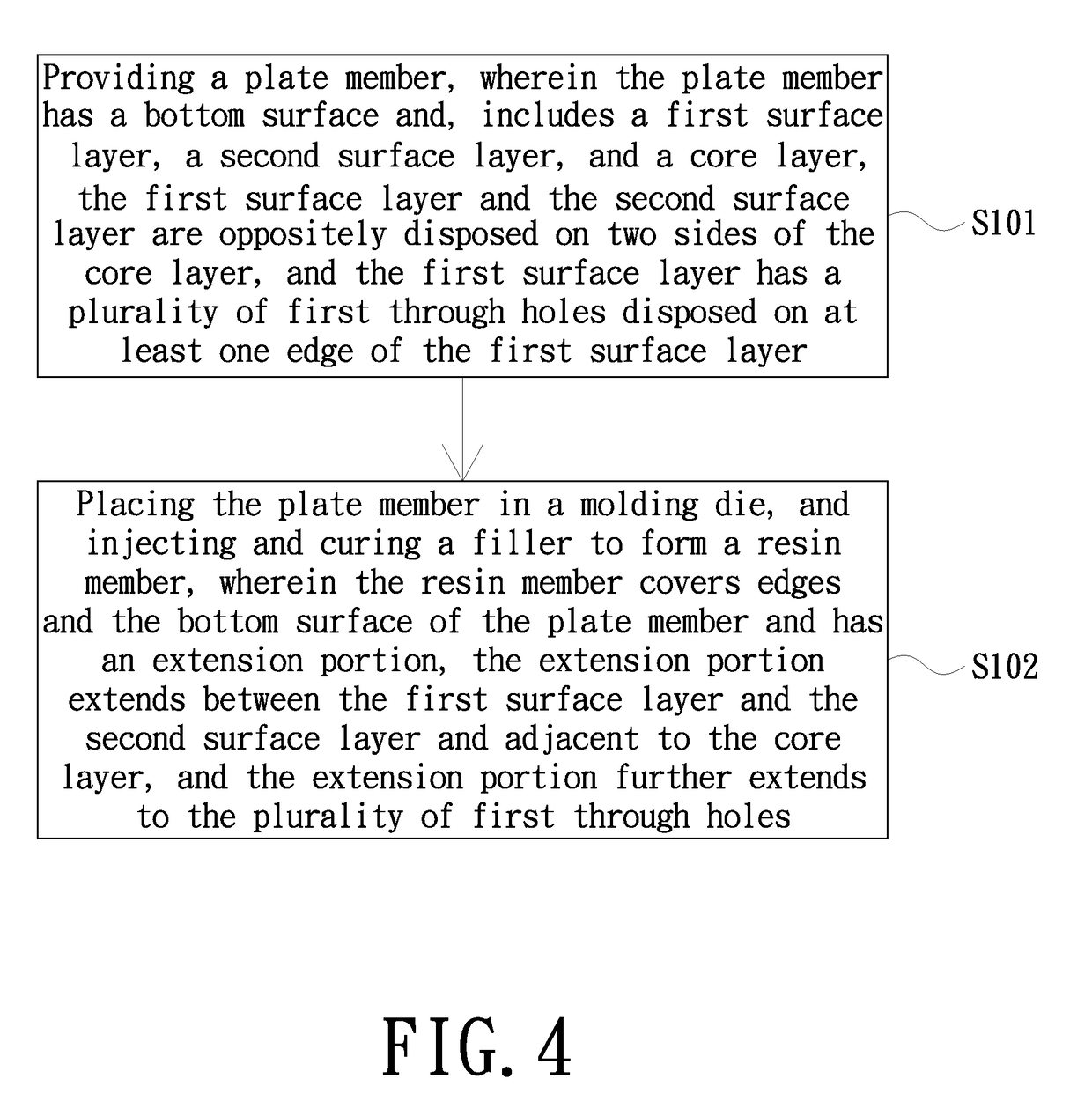
[0030]FIG. 1 is a schematic bottom view of a casing of an embodiment of the present invention. FIG. 2 is a schematic cross-sectional view taken along the line A-A′ of the casing of FIG. 1. FIG. 3 is a schematic view of a plate member of an embodiment of the present invention. Referring to FI...


PUM

PropertyMeasurementUnit
thicknessaaaaaaaaaa
thicknessaaaaaaaaaa
speedaaaaaaaaaa

Abstract

A casing including a plate member and a resin member is provided. The plate member has a bottom surface and includes a first surface layer, a second surface layer and a core layer. The first surface layer has a plurality of first through holes and disposed on at least one edge of the first surface layer. The first surface layer and the second surface layer are oppositely disposed on two sides of the core layer. The resin member covers edges and the bottom surface of the plate member and has an extension portion. The extension portion extends between the first surface layer and the second surface layer and adjacent to the core layer. The extension portion further extends to the plurality of first through holes. A manufacturing method of the casing is also provided.

Description

FIELD OF THE INVENTION[0001]The present invention relates to a casing, and more particularly to a casing composed of a plate member and a manufacturing method thereof.BACKGROUND OF THE INVENTION[0002]Among various electronic devices, computers have become an indispensable important product in human life. As technology advances, the functionality and speed of computers continue to grow, so that computers have developed from a large machine in the early days to desktops and notebooks.[0003]In terms of market trends, the two key requirements for notebook computer are volume reduction and weight reduction. In addition to the microelectronic components in the computer, the choice of computer casing materials is also the focus of development. The conventional notebook computer uses a plastic casing, and although the cost is inexpensive, it is obviously insufficient in strength after being thinned to reduce volume and weight. Therefore, other materials have been developed, such as the use ...

Claims


Application Information

Patent Timeline
Patent Type & Authority Applications(United States)
IPC IPC(8): G06F1/16B32B27/06
CPCG06F1/1633B32B27/065B32B2457/00G06F1/181G06F1/1613B32B15/088B32B3/02B32B2266/0264B32B2266/0228B32B27/12B32B2571/00B32B27/08B32B5/245B32B15/043B32B2262/062B32B2262/101B32B2262/106B32B27/34B32B2250/04B32B3/266B32B2266/025B32B15/046B32B27/20B32B5/18B32B5/26B32B7/12B32B2307/732B32B15/14B32B2266/0257
Inventor HUANG, HAN-CHINGLIN, PO-ANWU, JUNG-CHINLING, KUO-NAN
Owner COMPAL ELECTRONICS INC
Why Eureka
Try Eureka