Landing system for an aerial vehicle

Active Publication Date: 2019-01-24
GE AVIATION SYST LTD
View PDF7 Cites 4 Cited by
  • Summary
  • Abstract
  • Description
  • Claims
  • Application Information

AI Technical Summary

Benefits of technology

The present patent describes a landing system for controlling operation of an aerial vehicle flying a final approach to a runway. The system uses a LIDAR scanner mounted on the aerial vehicle and emits light to measure the distance between the vehicle and objects on the ground. The system obtains a first data set indicative of a reference flight path for the final approach and emits a second plurality of light beams when the aerial vehicle is flying the final approach. The system measures the time-of-flight of each light beam and compares it to the reference flight path to determine if the actual flight path deviates from the reference path. The system generates a control action to adjust the operation of the aerial vehicle until the actual flight path no longer deviates from the reference path. The technical effect of this system is to improve the accuracy and safety of landings by providing precise guidance and control to the aerial vehicle during the final approach phase.

Problems solved by technology

However, when the ground based components become inoperable (e.g., fail), aerial vehicles must be rerouted to another runway or, even worse, another airport.
Rerouting the aerial vehicles is undesirable, because the additional travel time increases fuel consumption.
In addition, the reputation of an airliner providing passenger services can be negatively impacted.

Method used


Image

  • Landing system for an aerial vehicle
  • Landing system for an aerial vehicle
  • Landing system for an aerial vehicle

Examples


Embodiment Construction

[0017]Reference will now be made in detail to present embodiments of the present disclosure, one or more examples of which are illustrated in the accompanying drawings. The detailed description uses numerical and letter designations to refer to features in the drawings.

[0018]As used herein, the terms “first” and “second” can be used interchangeably to distinguish one component from another and are not intended to signify location or importance of the individual components. The singular forms “a”, “an”, and “the” include plural references unless the context clearly dictates otherwise.

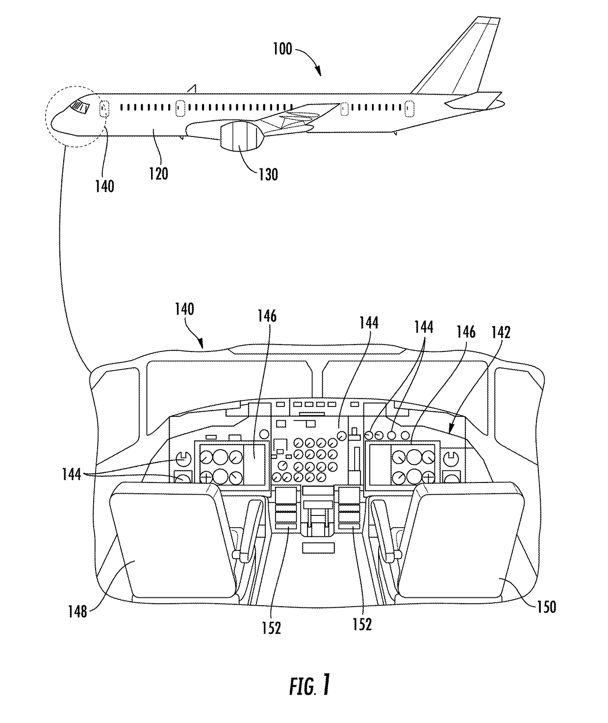
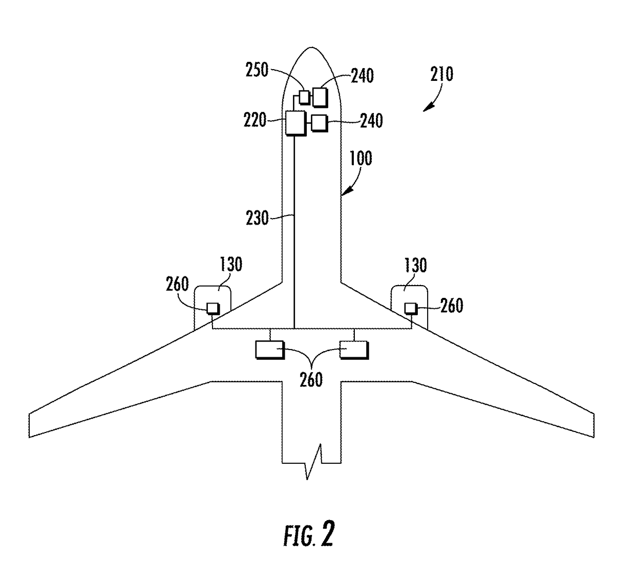
[0019]Example embodiments of the present disclosure are directed to a landing system for an aerial vehicle and a related method of using the landing system. Specifically, in example embodiments, the landing system can include a LIDAR scanner mounted to an aerial vehicle. The LIDAR scanner can include a light source and a sensor. The light source can emit a light beam that can be reflected off a surface a...


PUM


Abstract

A landing system for controlling operation of an aerial vehicle flying a final approach to a runway includes a computing device and a LIDAR scanner. The device obtains a first data set indicative of a reference flight path for the final approach. The first data set includes a time-of-flight measurement for each light beam of a first plurality of light beams emitted prior to the aerial vehicle flying the final approach. The device determines an actual flight path for the final approach based, at least in part, on a second data set comprising a time-of-flight measurement for each light beam of a second plurality of light beams emitted from the light source of the LIDAR scanner. Based on the first and second data sets, the device determines the actual flight path deviates from the reference flight path and generates a control action to adjust operation of the aerial vehicle.

Description

FIELD[0001]The present subject matter relates generally to aerial vehicles. In particular, the present subject matter relates to a landing system for aerial vehicles.BACKGROUND[0002]A landing system used to guide an aerial vehicle onto a runway includes components on the ground as well as onboard the aerial vehicle. However, when the ground based components become inoperable (e.g., fail), aerial vehicles must be rerouted to another runway or, even worse, another airport. In addition, if an airport does not include ground based components, aerial vehicles must be rerouted to another airport. Rerouting the aerial vehicles is undesirable, because the additional travel time increases fuel consumption. In addition, the reputation of an airliner providing passenger services can be negatively impacted.BRIEF DESCRIPTION[0003]Aspects and advantages of the present disclosure will be set forth in part in the following description, or may be obvious from the description, or may be learned throu...

Claims


Application Information

Patent Timeline
IPC IPC(8): G08G5/02G01S17/93G05D1/06G08G5/00G01S17/89G01S17/933
CPCG08G5/025G01S17/933G05D1/0676G08G5/0021G08G5/0047G05D1/10B64D45/04G01C23/005G01S17/89B64D45/08
Inventor SMITH, MARK ANDREW
Owner GE AVIATION SYST LTD
Why Eureka
Try Eureka