Method for mounting wall panels & wall panel system

a wall panel and wall panel technology, applied in the field of wall panel mounting and wall panel system, can solve the problem of difficult for a casual observer to see the joint between the first and second wall panels, and achieve the effect of masking any unevenness in the wall

Inactive Publication Date: 2019-01-31
RECO SURFACES
View PDF2 Cites 9 Cited by
  • Summary
  • Abstract
  • Description
  • Claims
  • Application Information

AI Technical Summary

Benefits of technology

[0017]A significant advantage of the invention is that the visual appearance of the gap filling sealant, when in its set condition, substantially matches the visual appearance of the textured surface of the protective film. The sealant provides sufficient visual continuity between the protective film of the first wall panel and the protective film of the second wall panel that it is difficult for a casual observer to see the joint between the first and second wall panels.
[0018]Sealants are sold in various colours such as white, brown and clear. The skilled person will readily understand what is meant by a “clear” sealant. In preferred methods the sealant includes silicone. Silicone sealants are commercially available, such as Soudal Silirub 2 S Silicone Sealant.
[0019]The sealant can be non-opaque. The sealant can be substantially transparent and / or translucent. The sealant can have a slightly cloudy appearance. Since clear sealant has a slightly cloudy appearance, side edges of the wall panels are not easily visible through the sealant. This is so, even in the case where the wall is uneven.
[0020]Typically the sealant substantially fills the gap between the first and second wall panels.
[0021]In preferred embodiments the protective film is substantially transparent.
[0022]Advantageously the textured surface of the film has a light scattering and / or light diffusing effect. This helps to mask any unevenness in the wall and hide the joint between the first and second wall panels.

Problems solved by technology

The sealant provides sufficient visual continuity between the protective film of the first wall panel and the protective film of the second wall panel that it is difficult for a casual observer to see the joint between the first and second wall panels.

Method used


Image

  • Method for mounting wall panels & wall panel system
  • Method for mounting wall panels & wall panel system
  • Method for mounting wall panels & wall panel system

Examples


example

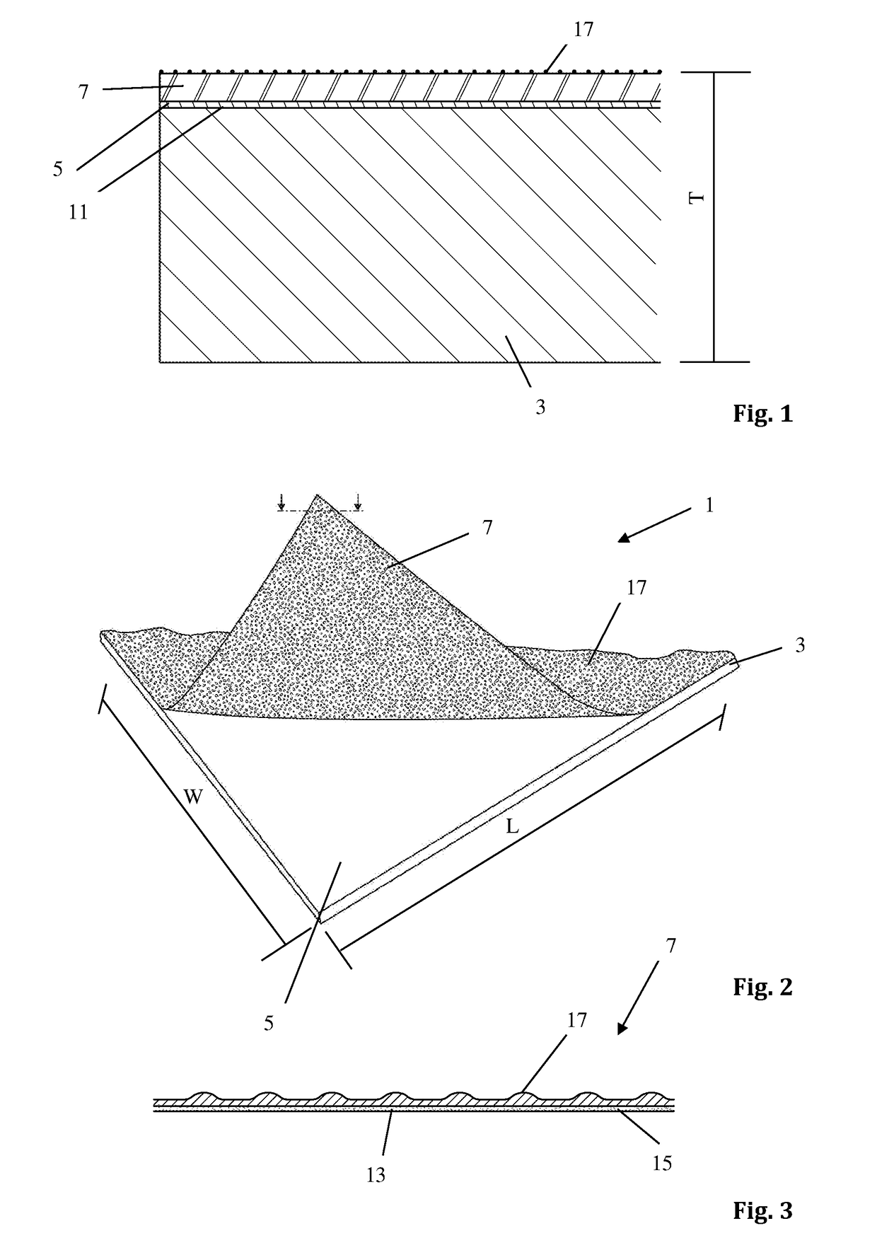
[0122]A preferred form of the wall panel 1 is arranged as follows: a PVC base layer 3 having a thickness of around 1000 μm, optional printed layer 5, and protective textured film 7 having a thickness of around 175 μm. Thus the total thickness of the wall panel is approximately 1.2 mm.

[0123]It has been found that this has arrangement has further advantages compared with prior art wall panels comprising solid sheet materials having thicknesses of around 2.0 mm to 2.5 mm. For example:[0124]1) Non-level walls and joins between panels are not noticeable on casual examination when the wall panels 1 are mounted in accordance with the method described below.[0125]2) The wall panel 1 weight is approximately half the weight of the prior art panels, which makes:[0126]A) It much easier to position the wall panel 1 accurately when fitting, the task can be achieved by one person rather than requiring two people, and the adhesive has less weight to support.[0127]B) The wall panel 1 is much more fl...


PUM

PropertyMeasurementUnit
thicknessaaaaaaaaaa
thicknessaaaaaaaaaa
thicknessaaaaaaaaaa

Abstract

A method for mounting wall panels (1a,1b) to a wall (27). The method including providing first and having a thermoplastics substrate (3) and a protective film (7) applied over a major surface (11) of the substrate, said protective film (7) having a thickness of at least 140 μm and including a textured surface (17) having a multiplicity of micro-peaks and/or micro-troughs randomly arranged, thereby providing a light diffusing and/or light scattering effect; mounting the first and second laminated wall panels (1a,1b) onto the wall (27); and inserting a gap filling sealant (21) into a gap between adjacent peripheral portions (29a,29b) of the first and second wall panels (1a,1b). A wall panel system is also disclosed.

Description

CROSS-REFERENCE TO RELATED APPLICATIONS[0001]The present application claims priority to PCT International Patent Application Serial No. PCT / GB2017 / 050191 filed Jan. 25, 2017 entitled “METHOD FOR MOUNTING WALL PANELS & WALL PANEL SYSTEM,” which claims the benefits of GB Patent Application Serial No. 1601435.9 filed Jan. 26, 2016, the entire disclosures of the applications being considered part of the disclosure of this application and hereby incorporated by reference.BACKGROUND OF THE INVENTION1. Field of the Invention[0002]The present invention relates to a method for mounting wall panels and a wall panel system.2. Description of the Prior Art[0003]Internal walls of buildings are paneled with a wide range of different materials in order to achieve the decorative effect and functionality required. Flat plastic sheets are often fitted as wall panels in areas where a decorative, easily cleanable surface is required. Typical examples are rigid sheets made from melamine formaldehyde or h...

Claims


Application Information

Patent Timeline
Patent Type & Authority Applications(United States)
IPC IPC(8): E04F13/08E04F13/18
CPCE04F13/0866E04F13/0885E04F13/0898E04F13/18B32B2307/40B32B27/08B32B9/045B32B7/12B32B13/06B32B13/12B32B15/082B32B15/10B32B15/20B32B21/08B32B27/22B32B27/28B32B27/302B32B27/304B32B27/308B32B27/36B32B3/06B32B3/30B32B2307/3065B32B2307/402B32B2307/41B32B2307/412B32B2307/414B32B2307/546B32B2307/584B32B2307/71B32B2307/72B32B2307/7265B32B2307/732B32B2307/748B32B2307/75B32B2607/02E04F13/0889
Inventor FLEET, CHARLES
Owner RECO SURFACES
Why Eureka
Try Eureka