Supercharge Your Innovation With Domain-Expert AI Agents!

Telegram splitting transmission method for bidirectional networks

a transmission method and network technology, applied in the field of data transmitters, can solve the problems of data loss, loss of synchronicity between base station and sensor node, data loss when transmitting, etc., and achieve the effect of reducing channel congestion, efficient data, and improving transmission

Inactive Publication Date: 2019-01-31
FRAUNHOFER GESELLSCHAFT ZUR FOERDERUNG DER ANGEWANDTEN FORSCHUNG EV +1
View PDF4 Cites 4 Cited by
  • Summary
  • Abstract
  • Description
  • Claims
  • Application Information

AI Technical Summary

Benefits of technology

The data transmitter described in this patent text can improve channel occupation or channel utilization by using the time gap between transmission data packets or between emitting two transmission data packets to emit one further transmission data packet. This improves the efficiency of data transmission in a network of low data throughput and high range. The transmission can be performed between any participants in the network, and simultaneously transmitting or receiving several transmissions can be facilitated. The method allows for prioritizing individual telegrams and relieving channels by specific performance or power adjustments. Omitting certain signals during transmission, such as a reference signal or downlink signal, can result in data loss, but the telegram splitting method prevents this by allowing for the transmission of multiple sub-packets while ensuring synchronicity between the base station and sensor nodes. The method also allows for simultaneous overlapping transmission from and to several other participants.

Problems solved by technology

However, caused by channels affected by interference, collisions and, consequently, data losses still occur when transmitting data between a large number of participants in a network of low data throughput and high range.
Omitting emissions of a reference signal or a downlink signal or an uplink signal in contrast results in losses in synchronicity between base station and sensor nodes or in data losses when transmitting.

Method used


Image

  • Telegram splitting transmission method for bidirectional networks
  • Telegram splitting transmission method for bidirectional networks
  • Telegram splitting transmission method for bidirectional networks

Examples


Embodiment Construction

[0054]In the following description of embodiments of the invention, equal elements or elements of equal effect in the figures are provided with equal reference numerals so that the description thereof in the different embodiments is mutually interchangeable.

[0055]However, before describing in detail embodiments of the inventive data transmitter and the inventive data receiver, an exemplary communications system where the data transmitter and the data receiver may be employed is shown making reference to FIG. 1.

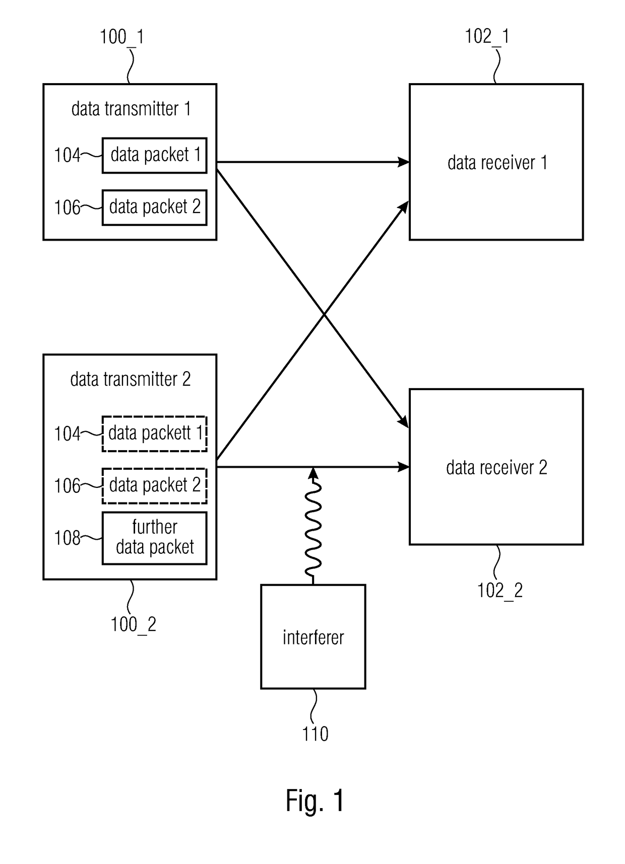
[0056]In detail, FIG. 1 shows a schematic view of a communications system having at least one data transmitter 100_1 and at least one data receiver 102_1. The communications system may optionally additionally comprise a second data transmitter 100_2, wherein in this case the data transmitter 100_1 is referred to as first data transmitter 100_1. Similarly, the communications system may optionally comprise a second data receiver 102_2, wherein in this case the data receiver 102_...


PUM


Abstract

A data transmitter is provided, having: a generator for generating transmission data packets, configured to split a first data packet destined for a first data receiver into at least two transmission data packets, wherein each of the transmission data packets destined for the first data receiver is shorter than the first data packet; a transmission element for transmitting data packets, configured to transmit the at least two transmission data packets destined for the first data receiver via a communications channel with a time gap; wherein the transmission element for transmitting data packets is configured to transmit at least one further transmission data packet to the first data receiver or a second data receiver in the time gap between the at least two transmission data packets destined for the first data receiver.

Description

CROSS-REFERENCE TO RELATED APPLICATIONS[0001]This application is a continuation of copending International Application No. PCT / EP2017 / 056829, filed Mar. 22, 2017, which is incorporated herein by reference in its entirety, and additionally claims priority from German Application No. 10 2016 205 052.4, filed Mar. 24, 2016, which is also incorporated herein by reference in its entirety.BACKGROUND OF THE INVENTION[0002]Embodiments of the present invention relate to a data transmitter, in particular to a data transmitter transmitting a data packet to a data receiver via a communications channel in a way split into several transmission data packets. Further embodiments relate to a data receiver, in particular to a data receiver receiving a data packet which is transmitted by a data transmitter via a communications channel in a way split into several transmission data packets. Some embodiments relate to an extension of the telegram splitting transmission method in order to utilize simultan...

Claims


Application Information

Patent Timeline
IPC IPC(8): H04L12/893H04L29/06H04L1/00H04L12/805H04L12/891H04L47/40H04L47/43H04L47/36H04L47/41
CPCH04L47/40H04L69/22H04L1/003H04L1/0007H04L47/365H04L47/41H04L1/008H04L2001/0093H04L1/0041H04L1/0071H04L69/28Y02D30/70
Inventor BERNHARD, JOSEFWECHSLER, JOHANNESKILIAN, GERDKNEI L, JAKOBROBERT, JORGHEUBERGER, ALBERT
Owner FRAUNHOFER GESELLSCHAFT ZUR FOERDERUNG DER ANGEWANDTEN FORSCHUNG EV
Features
  • R&D
  • Intellectual Property
  • Life Sciences
  • Materials
  • Tech Scout
  • Unparalleled Data Quality
  • Higher Quality Content
  • 60% Fewer Hallucinations
Learn More