
Multilayer substrate

Active Publication Date: 2019-01-31
MURATA MFG CO LTD
View PDF1 Cites 3 Cited by
  • Summary
  • Abstract
  • Description
  • Claims
  • Application Information

AI Technical Summary

Benefits of technology

This patent provides multilayer boards that have reliable connections between layers and are designed to reduce bending stresses on the connection conductor when subjected to bending force. The invention allows for space-saving and efficient use of space while maintaining high reliability.

Problems solved by technology

At this time, if an interlayer connection conductor is provided in the multilayer board, the interlayer connection conductor does not have flexibility, and thus peeling, etc. may occur at and around the interlayer connection conductor.
This may make it difficult to utilize this structure in a small-sized multilayer board.

Method used


Image

  • Multilayer substrate
  • Multilayer substrate
  • Multilayer substrate

Examples


first preferred embodiment

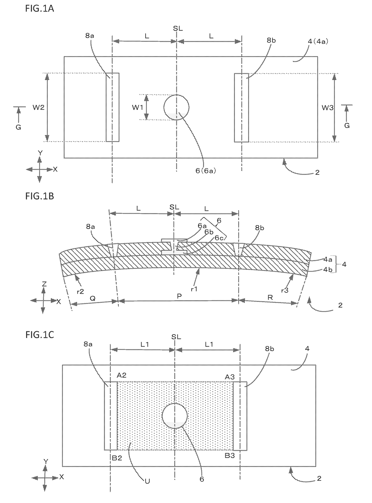
[0021]FIGS. 1A to 1C schematically show, in plan view and in cross section, a multilayer board 2 according to a first preferred embodiment of the present invention. FIG. 1A is a plan view, FIG. 1B is a cross sectional view taken along line G-G of FIG. 1A, and FIG. 1C is a reference plan view showing a positional relationship between an interlayer connection conductor and notches.

[0022]The multilayer board 2 according to the present preferred embodiment includes a flexible base material 4 including a plurality of laminated insulator layers 4a and 4b. In all of the views, with a Z-axis direction being a lamination direction, the flexible base material 4 is curved along an X-axis (referred to as “first direction”) that is one direction on a plane orthogonal or substantially orthogonal to the Z-axis direction (lamination direction). That is, the X-axis direction (first direction) is a bending direction of the flexible base material 4. Let a Y-axis direction (referred to as “second direc...

second preferred embodiment

[0053]FIGS. 4A to 4C schematically show in cross section and in plan view a multilayer board 2 according to a second preferred embodiment of the present invention.

[0054]In the present preferred embodiment, bottom surfaces S of the notches 8a and 8b in the Z-axis direction (lamination direction) are not coincident with a layer interface between the insulators 4a and 4b. Stress tends to concentrate on the layer interface between the insulator layers 4a and 4b, which layers become likely to peel off at the interface when subjected to a bending force. However, by not allowing the bottom surfaces S of the notches 8a and 8b to coincide with the layer interface between the insulator layers 4a and 4b as in the present preferred embodiment, peeling-off arising from the notches 8a and 8b is less likely to occur when subjected to the bending force.

[0055]The sectional view of FIG. 4A shows the case in which the bottom surfaces S of the notches 8a and 8b do not extend to the bottom of the upper ...

third preferred embodiment

[0059]FIG. 5 is a sectional view schematically showing a multilayer board according to a third preferred embodiment of the present invention.

[0060]In the present preferred embodiment, a notch pair 8ab (notches 8a and 8b) and a notch pair 8cd (notches 8c and 8d) are disposed on a first main surface 12 side and a second main surface 14 side, respectively, of the flexible base material 4.

[0061]By disposing the notch pairs 8ab and 8cd on the upper and lower surface sides, respectively, of the flexible base material 4 in this manner, it is possible to effectively disperse bending stress concentrating in the interlayer connection conductor 6 and its peripheral region when a bending force is applied to the flexible base material 4.

[0062]Although in FIG. 5 the case is shown in which the flexible base material 4 includes the two insulator layers 4a and 4b, similar effects to the above are able to be obtained by disposing the notch pairs on the first main surface side and the second main surf...


PUM


Abstract

A multilayer board includes a flexible base material including laminated insulator layers and curved along an X-axis direction on a plane orthogonal or substantially orthogonal to a lamination direction, an interlayer connection conductor on the flexible base material, and a notch pair on the flexible base material at positions symmetrical or substantially symmetrical in the X-axis direction with respect to a position of the interlayer connection conductor, the notch pair extending in a Y-axis direction orthogonal or substantially orthogonal to the X-axis direction on the plane. The interlayer connection conductor is within a region defined by the notch pair and lines respectively joining ends of the notch pair in the Y-axis direction. A radius of curvature of a region of the flexible base material between the notch pair in the X-axis direction being greater than curvature radii of regions outside of the notch pair.

Description

CROSS REFERENCE TO RELATED APPLICATIONS[0001]This application claims the benefit of priority to Japanese Patent Application No. 2017-000638 filed on Jan. 5, 2017 and is a Continuation Application of PCT Application No. PCT / JP2017 / 043987 filed on Dec. 7, 2017. The entire contents of each application are hereby incorporated herein by reference.BACKGROUND OF THE INVENTION1. Field of the Invention[0002]The present invention relates to a multilayer board that includes a plurality of insulator layers laminated together.2. Description of the Related Art[0003]Some multilayer boards each including a plurality of laminated insulator layers are flexible and bendable. At this time, if an interlayer connection conductor is provided in the multilayer board, the interlayer connection conductor does not have flexibility, and thus peeling, etc. may occur at and around the interlayer connection conductor.[0004]In order to cope with this, there has been proposed a multilayer board including an interla...

Claims


Application Information

Patent Timeline
IPC IPC(8): H05K1/02H05K3/46
CPCH05K1/0271H05K1/028H05K3/4652H05K2201/0939H05K2201/09063H05K3/0032H05K3/4069H05K3/0023H05K2203/068H05K2203/107H05K1/111H05K3/4617H05K2201/09827H05K2201/09854H05K2201/09945H05K2203/1572
Inventor OGURI, SHINYAITO, YUKIDOKAI, YUYAMORITA, ISAMU
Owner MURATA MFG CO LTD
Features
  • Generate Ideas
  • Intellectual Property
  • Life Sciences
  • Materials
  • Tech Scout
  • Unparalleled Data Quality
  • Higher Quality Content
  • 60% Fewer Hallucinations
Learn More