
Intelligent outdoor umbrella

a technology for outdoor umbrellas and umbrellas, applied in the field of intelligent outdoor umbrellas, can solve the problems of complex manufacturing of outdoor umbrellas with bent stems, inability to realize large angle and free degree adjustment, and high cost, and achieve the effects of simple and convenient operation, high degree of automation, and simple and convenient operation

Active Publication Date: 2019-02-07
LINHAI ZHONGTIAN ELECTRONICS APPLIANCE CO LTD
View PDF12 Cites 3 Cited by
  • Summary
  • Abstract
  • Description
  • Claims
  • Application Information

AI Technical Summary

Benefits of technology

The invention is an intelligent outdoor umbrella that can automatically adjust the angle of its cover and fold and unfold without any assistance from the user. It is easy to operate and has a simple structure that allows for convenient use.

Problems solved by technology

Such a structure cannot realize adjustment with large angle and free degree due to the limitation of the umbrella itself.
For the outdoor umbrella with a bent stem, the angle still cannot be adjusted conveniently, and it is impossible to adjust the angle by 360 degrees when the counterweight is in a certain position; and the process of manufacturing the outdoor umbrella with a bent stem is more complex, and it is not intelligent and is high in cost.

Method used


Image

  • Intelligent outdoor umbrella
  • Intelligent outdoor umbrella
  • Intelligent outdoor umbrella

Examples


embodiment 1

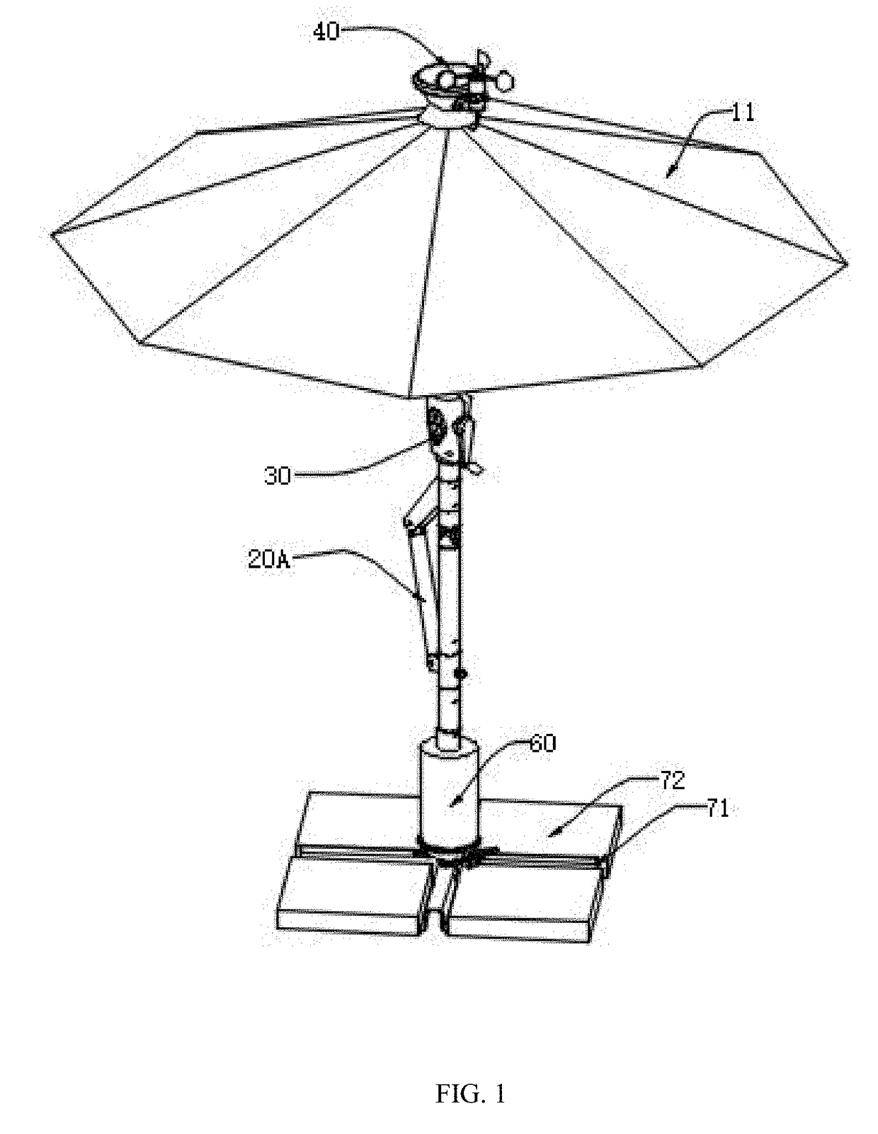
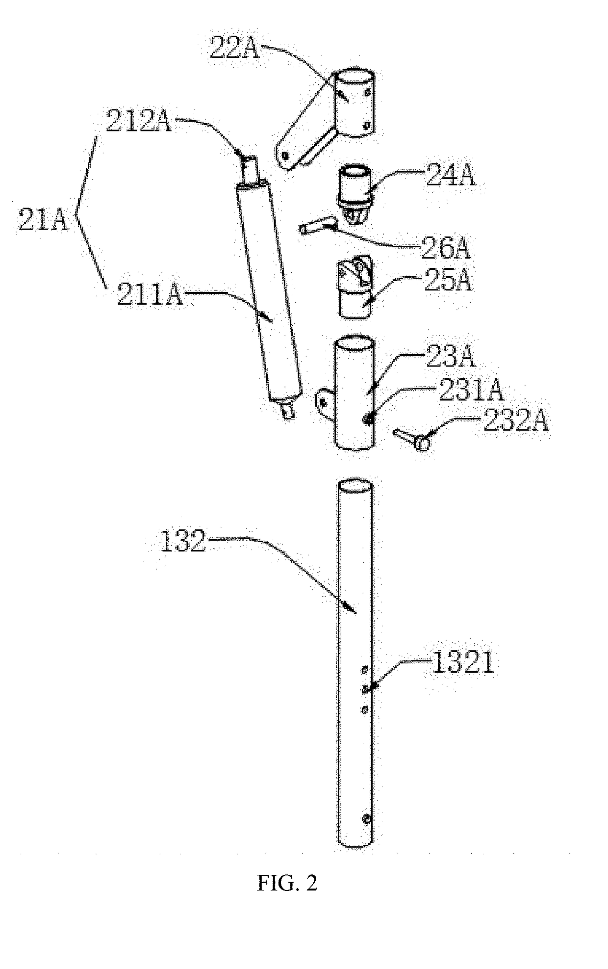
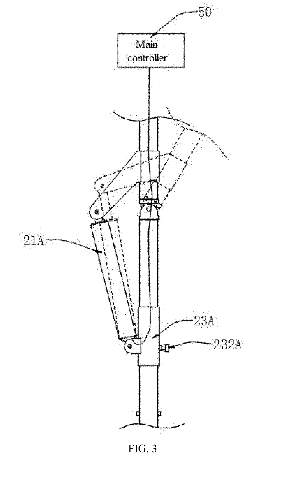
[0070]Referring to FIG. 1 to FIG. 4, in Embodiment 1, an angle adjustment mechanism 20A by which the angle can be manually adjusted and also can be automatically adjusted is disclosed. A structure by which the angle is automatically adjusted comprises a pushrod 21A, an upper connecting rod 22A, a lower connecting rod 23A, an upper connector 24A and a lower connector 25A; wherein the upper connector 24A is hinged to the lower connector 25A by a connecting pin 26A, the upper connector 24A is fixedly connected to the upper connecting rod 22A, and the lower connector 25A is fixedly connected to the lower connecting rod 23A; the pushrod 21A comprises a pushrod body 211A and a telescopic rod 212A, the pushrod body 211A is connected to the lower connecting rod 23A, and one end of the telescopic rod 212A is inserted into the pushrod body 211A and the other end thereof is fixedly connected to the upper connecting rod 22A; the pushrod 21A is connected to the main controller 50, and the main c...

embodiment 2

[0072]In Embodiment 2, referring to FIG. 5 to FIG. 8, the angle adjustment mechanism can perform adjustment only in two directions and this operation is simple. The present invention further discloses another angle adjustment mechanism 20B by which the angle can be adjusted by 360 degrees, comprising a pushrod 21B, a first connecting member 22B, a second connecting member 23B, a third connecting member 24B, an elastic hose 25B and a bearing assembly 26B, wherein the pushrod 21B, the first connecting member 22B, the second connecting member 23B, the third connecting member 24B and the bearing assembly 26B are all received within the elastic hose 25B. One end of the pushrod 21B is fixed on the third connecting member 24B and the other end thereof is connected to the first connecting member 22B after passing through the second connecting member 23B, and the bearing assembly 26B is arranged at a joint between the pushrod 21B and the first connecting member 22B; the pushrod 21B is connec...


PUM


Abstract

The present invention discloses an intelligent outdoor umbrella, comprising an umbrella body, an angle adjustment mechanism configured to adjust an angle in a vertical direction, a rotation mechanism configured to adjust an angle in a horizontal direction, a lifting mechanism, an environment monitoring mechanism and a main controller. An angle of an outdoor umbrella is automatically adjusted to follow the change in the sun angle and better achieve the purpose of shading. The lifting mechanism enables the outdoor umbrella to fold and unfold automatically. The environment monitoring mechanism comprises a solar assembly and a wind speed measurement device, the direction of sunlight and the wind speed are monitored and the measured related data is transmitted to the main controller. The present invention is simple and convenient without manual operation.

Description

TECHNICAL FIELD[0001]The present invention relates to the technical field of outdoor leisure and shading supplies and in particular to an intelligent outdoor umbrella.BACKGROUND OF THE PRESENT INVENTION[0002]An outdoor umbrella is a common shading supply in travel and leisure. It is simple to use and the umbrella cover folds and unfolds quickly and deftly. It offers a comfortable and cool space for people in outdoor activities. Since the stem is out of the umbrella, when the umbrella cover unfolds, the umbrella cover is high off the ground, the space below the umbrella cover is large, and the shading effect is great. Usually, for such an outdoor umbrella, a crank structure is arranged on the stem, and the rope is tightened or loosened by rotating the crank to control the umbrella cover to fold or unfold.[0003]In an existing outdoor umbrella, the angle adjustment mechanism is simple and generally mechanical. For example, a tilting structure is provided on the bottom of the umbrella s...

Claims


Application Information

Patent Timeline
Patent Type & Authority Applications(United States)
IPC IPC(8): A45B25/14A45B17/00
CPCA45B25/143A45B17/00A45B2025/003A45B2200/1009A45B23/00A45B25/00A45B2023/0012A45B2023/0093A45B2200/1027A45B2200/1081F16H1/222
Inventor JIN, SHIMIN
Owner LINHAI ZHONGTIAN ELECTRONICS APPLIANCE CO LTD
Learn More