
Multiphase production boost method and system

a hydrocarbonbearing fluid and multi-phase technology, applied in the direction of positive displacement liquid engine, piston pump, borehole/well accessories, etc., can solve the problems of mainly breaking down along cost, complexity and reliability, and operators typically experiencing poor uptime and frequent maintenance, and achieve high reliability, high energy efficiency, and high power efficiency

Active Publication Date: 2019-02-07
SAUDI ARABIAN OIL CO
View PDF10 Cites 0 Cited by
  • Summary
  • Abstract
  • Description
  • Claims
  • Application Information

AI Technical Summary

Benefits of technology

[0009]It is desirable to have a system and a method for handling low-pressure multiphase production fluid to produce a high-pressure multiphase fluid where reliability and efficiency are improved over the use of a multi-phase pump system. A reduction in overall operating costs not only in more consistent production but also by using technology that is more reliable and well-known is also viewed as an improvement.
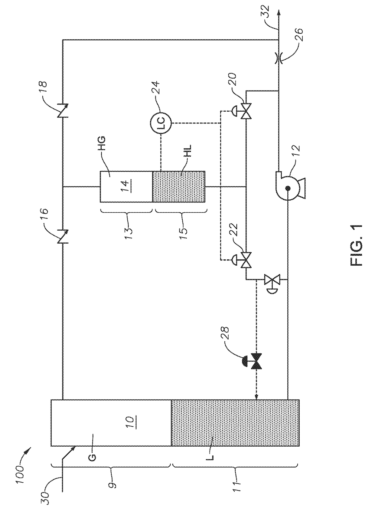
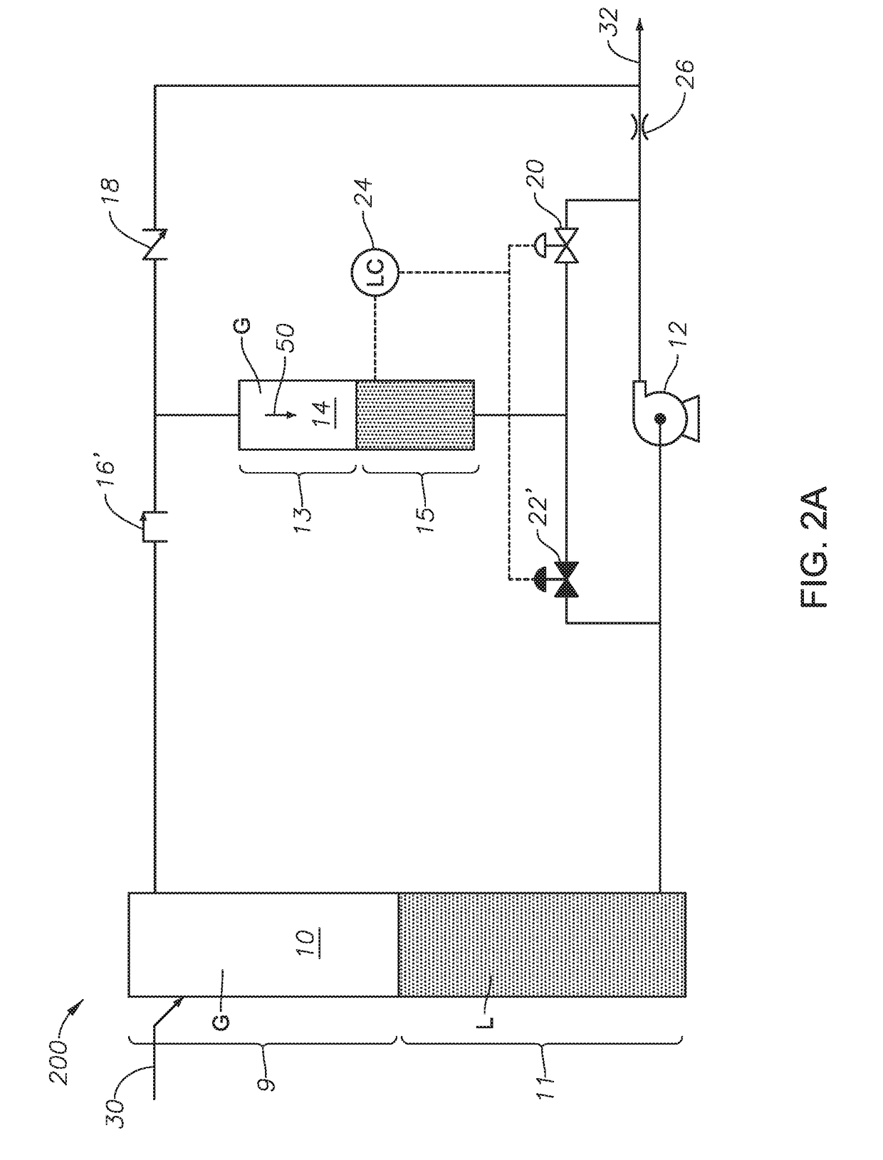
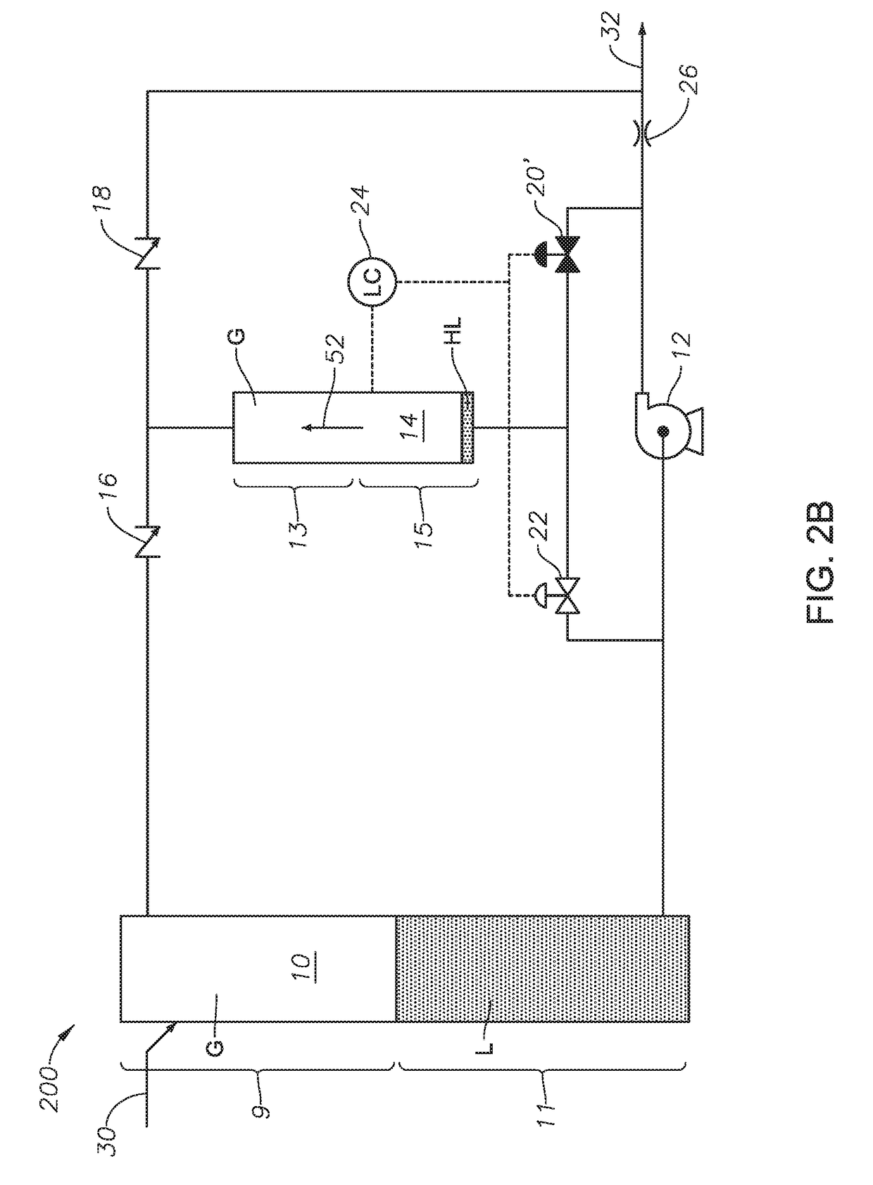
[0011]In alternate embodiments, the liquid portion of the liquid piston compressor can also couple to the liquids pump such that there is one-way fluid communication of a reduced pressure liquid from the liquid piston compressor to the liquids pump. The liquid portion of the liquid piston compressor can alternately couple to the gas-liquid separator such that there is one-way fluid communication of a reduced pressure liquid from the liquid piston compressor to the gas-liquid separator. The system can be operable to maintain the liquid piston compressor in a substantially isothermal condition. The substantially isothermal condition can be maintained using the low-pressure liquid from the gas-liquid separator.
[0015]The methods and the systems disclosed herein are for boosting production of a multi-phase fluid comprising crude oil, natural gas and formation water. The systems separate the gas-liquid mixture into a low-pressure gas and a low-pressure liquid. A conventional-type liquid pump is used to increase the pressure of the liquid, which is a combination of crude oil and formation water, to a high-pressure liquid. The gas pressure is boosted using a liquid piston compressor, where the liquid driving the liquid piston compressor is the high-pressure liquid. The high-pressure gas and the high-pressure liquid are recombined into a multi-phase product and passed from the system. Optionally, the liquid piston compressor is operable to cool such that isothermal or near-isothermal compression occurs. The systems offer compactness, higher reliability and higher energy efficiency with well-understood and reliable components.
[0016]The systems offer a solution by permitting the use of known separators and standard liquid pumps to handle a multiphase production. The low-pressure gas is separated before the intake of the liquids pump and it is reintroduced after the high-pressure liquid discharges. The low-pressure gas is compressed using the liquid piston compressor that optionally may operate under near-isothermal to isothermal gas conditions to achieve a high power efficiency. Liquid piston compression overcomes the poor heat transfer issue associated with typical mechanical compressions such as reciprocating piston compressors, and the lack of moving mechanical parts adds reliability to the operating system.

Problems solved by technology

There are issues with using MPP technology.
Common issues with the technologies mainly break down along cost, complexity and reliability.
Operators typically experience poor uptime and frequent maintenance during initial installation and break-in.
The software and control systems for dynamic operations may be inadequate to handle the unstable dynamic behavior of the well, leading to frequent “tripping” and shutdown.
This low efficiency production avoids over-heating due to prolong gas flow, which has poor heat transfer and lubrication compared to crude oil.

Method used


Image

  • Multiphase production boost method and system
  • Multiphase production boost method and system
  • Multiphase production boost method and system

Examples


Embodiment Construction

[0024]The Specification, which includes the Summary of Disclosure, Brief Description of the Drawings and the Detailed Description of the Preferred Embodiments, and the appended Claims refer to particular features (including process or method steps) of the embodiments of this disclosure. Those of skill in the art understand that the embodiments of this disclosure include all possible combinations and uses of particular features described in the Specification. Those of skill in the art understand that the disclosure is not limited to or by the description of embodiments given in the Specification. The inventive subject matter is not restricted except only in the spirit of the Specification and appended Claims.

[0025]Those of skill in the art also understand that the terminology used for describing particular embodiments does not limit the scope or breadth of the disclosure. In interpreting the Specification and appended Claims, all terms should be interpreted in the broadest possible m...


PUM


Abstract

A system and method for boosting the pressure of a low-pressure multiphase mixture into a high-pressure multiphase mixture. The system includes a gas-liquid separator, a liquids pump and a liquid piston compressor. The method includes introducing the low-pressure multiphase mixture into the pressure boost system, operating such that a low-pressure liquid and a low-pressure gas form, boosting the pressure of the low-pressure liquid to a high-pressure liquid, introducing low-pressure gas during a charging period into the liquid piston compressor, converting the low-pressure gas into high-pressure gas using the high-pressure liquid during a compression period, discharging the high-pressure gas form the liquid piston compressor, and mixing the high-pressure liquid and gas such that the high-pressure multiphase mixture.

Description

CROSS REFERENCE TO RELATED APPLICATIONS[0001]This application is a divisional of, and claims priority to and the benefit of co-pending U.S. application Ser. No. 14 / 956,643, filed Dec. 2, 2015, titled “Multiphase Production Boost Method and System,” which claims priority to and the benefit of co-pending U.S. Provisional Application No. 62 / 088,749, titled “Multiphase Production Boost Method and System,” filed Dec. 8, 2014, the full disclosure of each which is hereby incorporated by reference herein in its entirety for all purposes.BACKGROUND OF THE DISCLOSURE1. Field of the Disclosure[0002]The field of disclosure relates to the production of a multiphase hydrocarbon-bearing fluid. More specifically, the field relates to boosting the pressure of the hydrocarbon-bearing fluid with pumps and compressors.2. Description of the Related Art[0003]Oil and gas production often starts with high reservoir pressure that allows a well to produce oil, gas or a combination of both, naturally. The pro...

Claims


Application Information

Patent Timeline
Patent Type & Authority Applications(United States)
IPC IPC(8): F04B19/06F04B41/00F04B39/06F04B23/06F04B39/00
CPCF04B41/00F04B39/06F04B19/06F04B23/06F04B39/0011F04B9/103E21B43/36Y10T137/86155F04B49/002E21B43/34E21B21/067F04B23/08
Inventor XIAO, JINJIANGWANG, SHOUBO
Owner SAUDI ARABIAN OIL CO
Learn More