Force measurement system for exercise equipment

Active Publication Date: 2019-02-07
DIRECTION TECH
View PDF5 Cites 3 Cited by
  • Summary
  • Abstract
  • Description
  • Claims
  • Application Information

AI Technical Summary

Benefits of technology

[0014]According to the structure of the present invention, the user directly applies a force on the measured body, wherein the degree of force applied by the user is positively related to the deformation amount of the measured body, that is, the greater the work performed by the user on the exercise equipment, the larger the deformation amount of the measured body, and the greater the amount of change in the resistan

Problems solved by technology

Since the damping of the exercise equipment in motion is not completely consumed by the user, and some of the work done by the use

Method used


Image

  • Force measurement system for exercise equipment
  • Force measurement system for exercise equipment
  • Force measurement system for exercise equipment

Examples


first embodiment

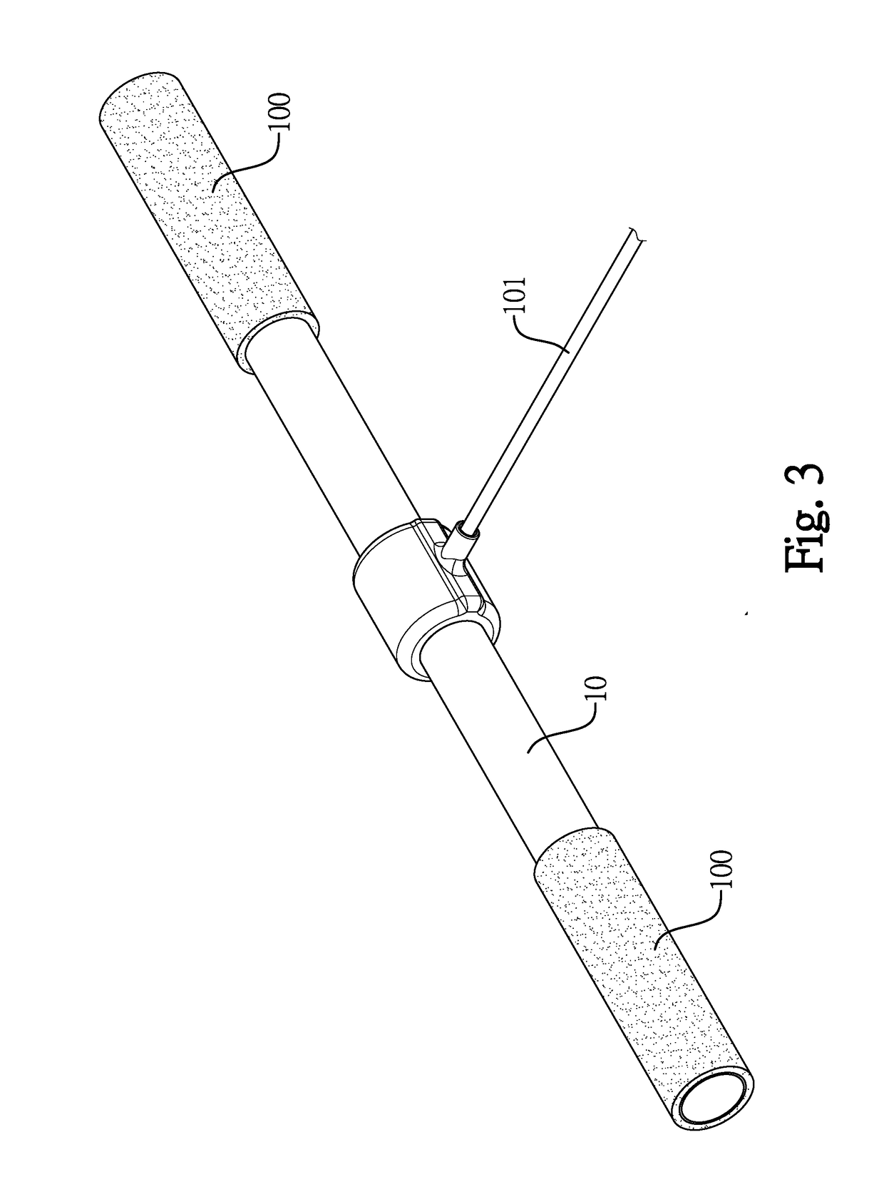
[0037]Please refer to FIG. 3 and FIG. 4 , a measured body 10 can be a long rod. Two opposite ends of the long rod are respectively grips 100, and the grips 100 are for the user to hold. A center of the measured body 10 is connected to a rope 101, and the rope 101 is connected to a load unit (for example, a load block) through a transmission mechanism such as a pulley. The user can pull the measured body 10 to lift the load unit or drive the load unit to move. Please refer to FIG. 4, the four force sensors 30 can be attached to a surface of the measured body 10, two of the force sensors 30 are disposed on the surface of the measured body 10 and adjacent to an outer circumference of the rope 101, the other two force sensors 30 are respectively disposed oppositely to the aforementioned two force sensors 30. When the user pulls the measured body 10, the grips 100 at the two opposite ends of the measured body 10 are subjected to a pulling force applied by the user, and the center of the ...

second embodiment

[0038]Please refer to FIG. 5 and FIG. 6 showing a measured body 20. The measured body 20 can be a plate-shaped block being roughly circular and having a thickness, and can be a member made of an aluminum alloy. The measured body 20 comprises a first connecting end portion 201, a second connecting end portion 202, a first outer peripheral surface 203, a second outer peripheral surface 204, two side surfaces 205, a recess 206, a first slot 207 and a second slot 208. An end face of the first connecting end portion 201 and an end face of the second connecting end portion 202 are oppositely disposed and can respectively have setting holes 201a, 202a. The first outer peripheral surface 203 and the second outer peripheral surface 204 are oppositely disposed and connected to the first connecting end portion 201 and the second connecting end portion 202 respectively. The two side surfaces 205 are two opposite sides, and can be perpendicular to the planes of the first outer peripheral surface...

third embodiment

[0041]Please refer to FIG. 11, a measured body 60 can be a pulley. The pulley is disposed with a sleeve 61 at a center thereof. The sleeve 61 is provided for installing a shaft of the exercise equipment, wherein the diameter of the sleeve 61 is smaller than the diameter of the measured body 60 (pulley). An outer peripheral surface of the measured body 60 (pulley) is formed with a first fillister for disposing a first rope 62, and one end of the first rope 62 is fixed in the first fillister of the measured body 60 (pulley) by a first fixing member 620. An outer peripheral surface of the sleeve 61 can be formed with a second fillister for disposing a second rope 63, and one end of the second rope 63 is fixed in the second fillister of the sleeve 61 by a second fixing member 630. The four force sensors 30 are disposed on a side of the measured body 60 (pulley) at equal intervals along a circumference, and a center position of the circumference is an axial position of the shaft of the m...


PUM


Abstract

A force measuring system for exercise equipment provided for using in an exercise equipment, the system includes a measured body, a force sensor, a circuit board; a Wheatstone bridge, a data transmission module and a power module disposed on the circuit board; and a receiving device. The power module provides a working power supply. The measured body is connected to the exercise equipment. The force sensor is disposed on the measured body, and the resistance value thereof changes along with a deformation amount of the measured body. The Wheatstone bridge is electrically connected to the force sensor to output a measurement signal. The data transmission module transmits a force taken information to the receiving device, wherein the force taken information is obtained according to the measurement signal.

Description

REFERENCE TO RELATED APPLICATIONS[0001]The present application is based on, and claims priority from, Taiwan application number 106125944, filed 2017 Aug. 1, the disclosure of which is hereby incorporated by reference herein in its entirety.BACKGROUND OF THE INVENTIONField of the Invention[0002]The present invention relates to a force measuring system for exercise equipment and more particularly to a force measuring system for exercise equipment capable of connecting to an exercise equipment and directly reflecting the work done by the user on the exercise equipment.Description of the Prior Art[0003]In traditional exercise equipment that provides weight training for users, the pulling or lifting force is mainly indirectly referenced to the weight of weight stacks on the exercise equipment; or, in traditional rowing machines or other exercise equipment, the torque measurement can only be indirectly converted from the data of its generator or brake resistance system.[0004]In can be kn...

Claims


Application Information

Patent Timeline
IPC IPC(8): G01L1/22G01L5/00
CPCG01L1/2293G01L5/0033A63B24/0087A63B21/06A63B71/0619A63B2220/51G01L1/2237
Inventor CHEN, YU-YU
Owner DIRECTION TECH
Why Eureka
Try Eureka