Compressor rotor blade, compressor, and method for profiling the compressor rotor blade

a compressor and rotor blade technology, applied in the direction of non-positive displacement pumps, axial flow pumps, fluid engines, etc., can solve the problems of reducing the degree of efficiency of compressors, and achieve the effect of increasing the degree of compressor efficiency

Active Publication Date: 2019-02-14
SIEMENS ENERGY GLOBAL GMBH & CO KG
View PDF11 Cites 0 Cited by
  • Summary
  • Abstract
  • Description
  • Claims
  • Application Information

AI Technical Summary

Benefits of technology

[0014]The camber line of the profile section is advantageously shifted when said profile section is changed, in particular only the camber line is shifted. This advantageously achieves a situation where the width of the duct remains unchanged between two compressor rotor blades which are arranged adjacently in a rotor blade ring. It is advantageous that the geometric model, before the change of the profile section, is of exclusively concave configuration on the pressure side of said profile section and/or is of exclusively convex configuration on the suction side of said profile section.
[0015]It is advantageous that the profile section is changed in such a way that the progression of the curvature has a maximum value in the convex suction side region, which maximum value is greater than the maximum value of the progression of the curvature in the corresponding region of the conventional compressor rotor blade. The profile section is advantageously changed in such a way that the progression of the curv

Problems solved by technology

The losses bring about a reduction in th

Method used


Image

  • Compressor rotor blade, compressor, and method for profiling the compressor rotor blade
  • Compressor rotor blade, compressor, and method for profiling the compressor rotor blade
  • Compressor rotor blade, compressor, and method for profiling the compressor rotor blade

Examples


Embodiment Construction

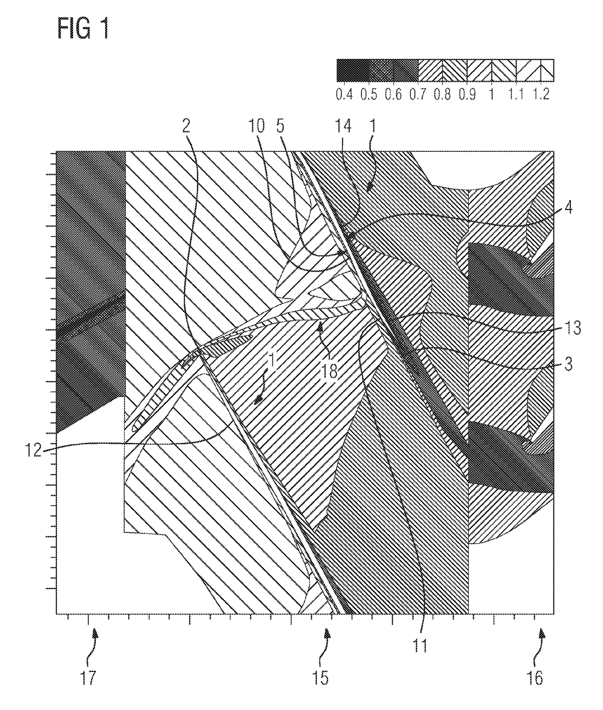
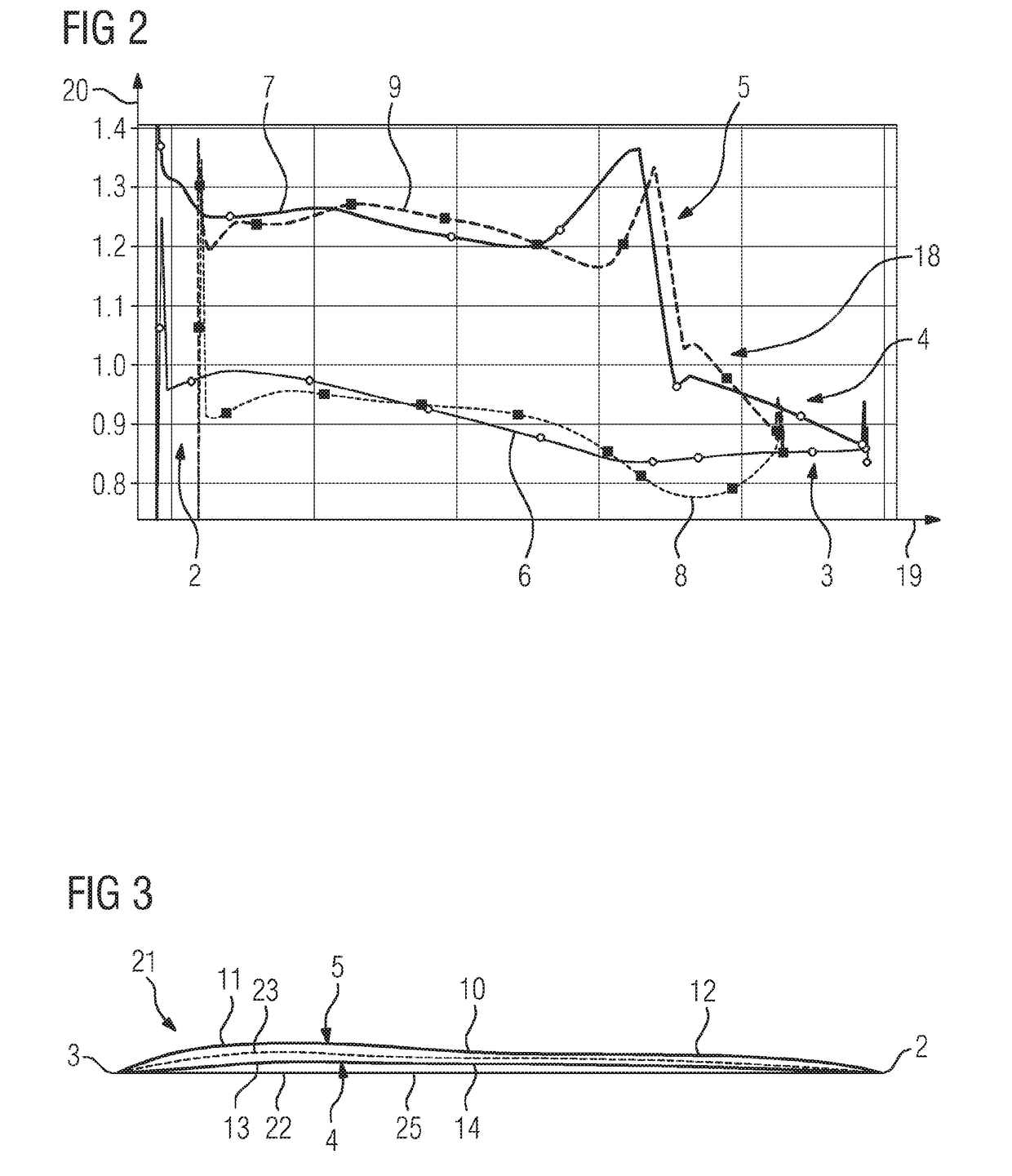
[0022]As can be seen from FIGS. 1 and 3, a compressor rotor blade 1 for a compressor of axial design has a blade profile. The blade profile has a radially inner subsonic section and a radially outer transonic section, only the transonic section being shown in FIGS. 1 and 3. The blade profile has a profile section 21 which extends in the transonic section. For example, the profile section 21 lies on a cylindrical surface, the axis of which coincides with the axis of the compressor, on a conical surface, the axis of which coincides with the axis of the compressor, on an S1 flow surface of the compressor, or in a tangential plane of the compressor.

[0023]The profile section 21 has a front edge 2, a rear edge 3, a pressure side 4 and a suction side 5. In FIG. 3, a profile chord 22 is illustrated, in addition, which profile chord 22 extends as a straight line from the front edge 2 as far as the rear edge 3. Furthermore, FIG. 3 shows a camber line 23 which extends from the front edge 2 as ...


PUM


Abstract

A compressor rotor blade for an axial-type compressor has a blade profile having a transonic section and a profile section which extends in the transonic section and has concave and convex suction-side regions on the suction side, the convex suction-side region arranged downstream of the concave suction-side region, and has convex and concave pressure-side regions on the pressure side, the concave pressure-side region arranged downstream of the convex pressure-side region. Curvature progressions on the pressure side and on the suction side are both applied in a continuous manner over a profile chord of the profile section, the positions of the minimum values of the curvature progressions deviate from each other by not more than 10% of the length of the profile chord, and the positions of the maximum values of the curvature progressions deviate from each other by not more than 10% of the length of the profile chord.

Description

CROSS REFERENCE TO RELATED APPLICATIONS[0001]This application is the US National Stage of International Application No. PCT / EP2017 / 050453 filed Jan. 11, 2017, and claims the benefit thereof. The International Application claims the benefit of European Application No. EP16155063 filed Feb. 10, 2016. All of the applications are incorporated by reference herein in their entirety.FIELD OF INVENTION[0002]The invention relates to a compressor rotor blade and to a method for profiling the compressor rotor blade.BACKGROUND OF INVENTION[0003]A compressor of axial design has at least one rotor blade ring with a plurality of compressor rotor blades for compressing a working medium. The compressor rotor blade has a radially inner subsonic section, in which the compression takes place by means of a deflection of the flow of the working medium. Furthermore, the compressor rotor blade has a transonic section, in which the compression takes place predominantly by means of a compression shock, in th...

Claims


Application Information

Patent Timeline
IPC IPC(8): F04D21/00F04D19/00F04D29/32F04D29/38
CPCF04D21/00F04D19/00F04D29/324F04D29/384F04D29/681F05D2240/302F05D2240/305F05D2240/306
Inventor CORNELIUS, CHRISTIANSTARKE, CHRISTOPH
Owner SIEMENS ENERGY GLOBAL GMBH & CO KG
Why Eureka
Try Eureka