
Pendulum vibration damper

Active Publication Date: 2019-02-14
TOYOTA JIDOSHA KK
View PDF2 Cites 5 Cited by
  • Summary
  • Abstract
  • Description
  • Claims
  • Application Information

AI Technical Summary

Benefits of technology

This patent is about a device called a pendulum vibration dampener. The device prevents the retainer from tilting or moving in the axial direction, which would cause problems with its operation. The device uses a restriction member that comes into contact with the inner face of the casing or the retainer to restrict movement. This prevents the retainer from holding the rolling masses in the correct posture and ensures accurate operation. The device also includes a stopper portion that allows the rolling masses to balance on when the device is rotated slowly or stopped. The locking mechanism is designed to be lightweight and compact.

Problems solved by technology

Consequently, the rolling mass may be disengaged from the retainer, or the retainer may be jammed between the rolling mass and the casing.
As a result, the rolling mass may not be held properly by the retainer, and hence the rolling mass may not be allowed to oscillate along a designed orbit.

Method used


Image

  • Pendulum vibration damper
  • Pendulum vibration damper
  • Pendulum vibration damper

Examples


Embodiment Construction

)

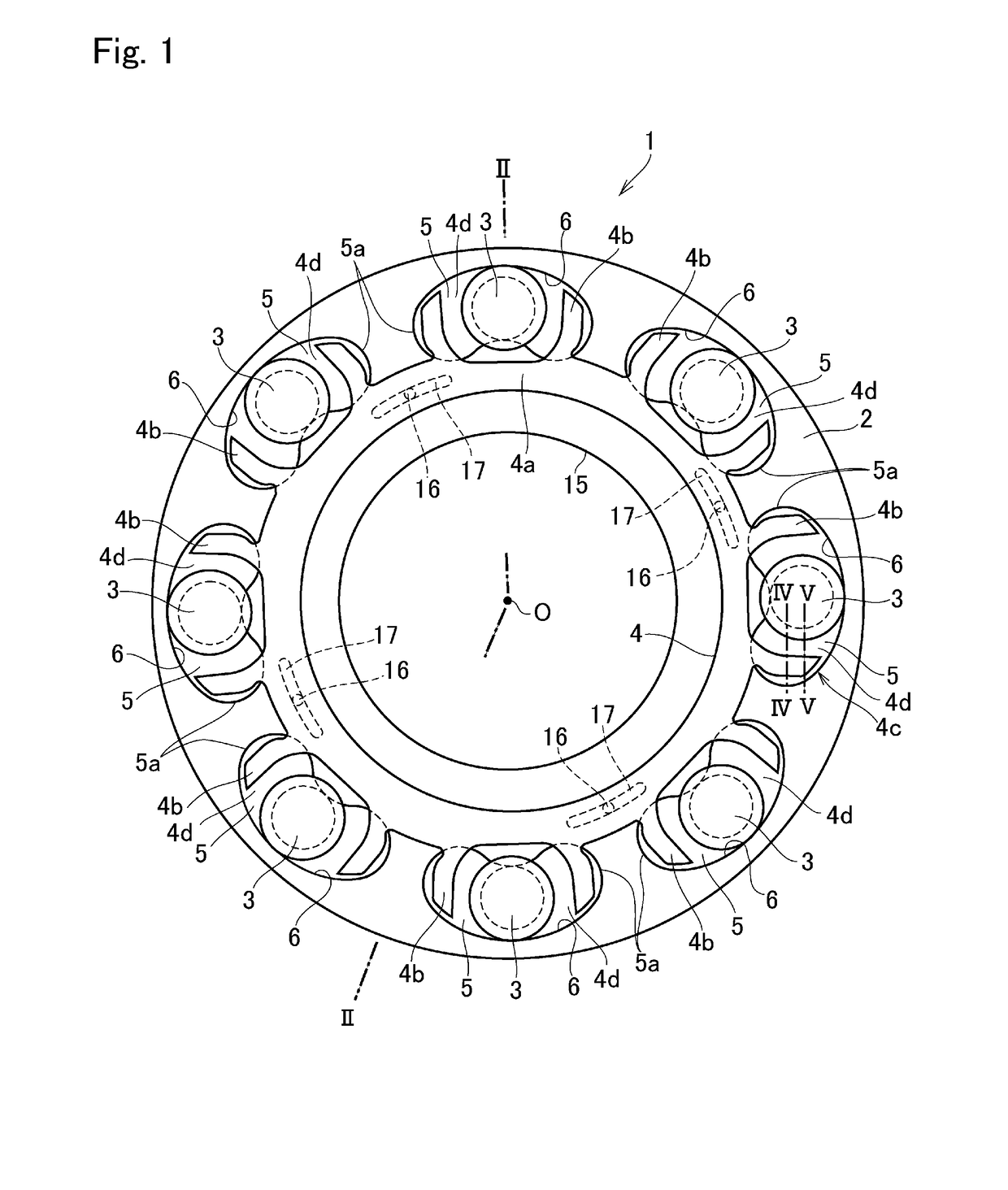
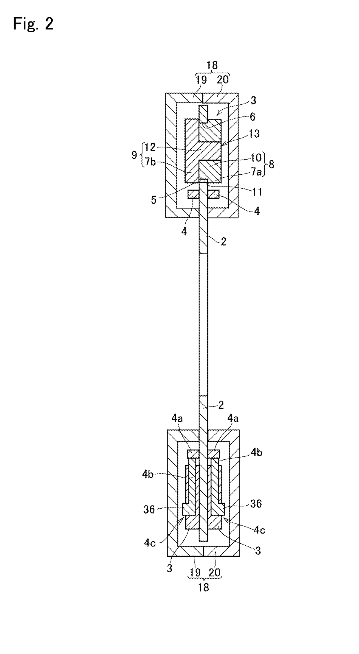
[0030]Preferred embodiments of the present application will now be explained with reference to the accompanying drawings. Turning now to FIG. 1, there is shown a preferred embodiment of the pendulum vibration damper 1 for suppressing torsional vibrations in a vehicle resulting from pulsation of torque of an engine by oscillating motions of masses. The pendulum vibration damper 1 comprises a rotary disc 2 that is rotated by the torque of the engine, a plurality of rolling masses 3 held in the rotary disc 2, and a ring-shaped retainer 4 having a plurality of holder portions 4d individually holding the rolling mass 3 therein.

[0031]The rotary disc 2 is an annular plate member having a center hole 15, and a crankshaft of the engine, a propeller shaft, or an axle shaft for transmitting torque to a drive wheel (neither of which are shown) are inserted into the center hole 15. That is, the rotary disc 2 is mounted on the crankshaft, the propeller shaft, or the axle shaft to be rotated inte...


PUM


Abstract

A pendulum vibration damper in which a retainer is prevented from being moved or tilted in an axial direction. In the pendulum vibration damper, a restriction member formed on any one of the retainer and an inner face of the casing to be brought into contact to the other one of the retainer and the inner face of the casing when the retainer is moved or tilted in an axial direction of the rotary disc. A clearance between the casing and the rolling mass in the axial direction is shorter than a thickness of the retainer in the axial direction.

Description

[0001]The present invention claims the benefit of Japanese Patent Application No. 2017-153978 filed on Aug. 9, 2017 with the Japanese Patent Office, the disclosure of which is incorporated herein by reference in its entirety.BACKGROUNDField of the Invention[0002]The present invention relates to the art of a torsional vibration damper that suppresses torsional vibrations by a pendulum motion of a inertia mass.Discussion of the Related Art[0003]JP-A-2016-114170 describes one example of a torsional vibration damper. In the damper taught by JP-A-2016-114170, a plurality of chambers are formed in a rotary disc, and a rolling mass is individually held in each of the chambers. When the rotary disc is rotated, each of the rolling mass is centrifugally pushed onto a raceway surface of the chamber while being oscillated by torque pulses, and torsional vibrations resulting from the torque pulses are damped by the oscillating motions of the rolling masses.[0004]The damper taught by JP-A-2016-11...

Claims


Application Information

Patent Timeline
IPC IPC(8): F16F15/14F16F15/31
CPCF16F15/145F16F15/31F16F2222/08F16F2232/02F16H2045/0263F16H45/02F16F15/1407
Inventor NISHIDA, HIDEYUKIAMANO, HIROYUKIHORITA, SHUHEISUZUKI, YUJI
Owner TOYOTA JIDOSHA KK
Learn More