Motor control device and motor control method

a technology of motor control and control device, which is applied in the direction of dynamo-electric converter control, dynamo-electric gear control, instruments, etc., can solve the problems of large battery power consumption, and achieve the effect of suppressing the vibration caused by drive shaft torsion and suppressing battery power consumption

Active Publication Date: 2016-10-04
NISSAN MOTOR CO LTD
View PDF8 Cites 3 Cited by
  • Summary
  • Abstract
  • Description
  • Claims
  • Application Information

AI Technical Summary

Benefits of technology

[0006]When the above-described method for controlling an induction motor is applied in a case of the torque command being set to damp drive shaft torsion when, for example, the vehicle is on a steep slope or the like and the drive shaft twists and the vehicle starts off after having been stopped, the magnetic flux command is set from a torque command of 0, and torque that damps the twisting can therefore be outputted with high responsiveness to the command value.
[0009]The present invention solves the above problem by using a detection means (device) for detecting the releasing of a lock mechanism for locking the rotation of the vehicle wheels, suppressing the torsional vibration of the drive shaft, controlling the current channeled to a motor on the basis of a motor torque command value set by a damping control means (device), and channeling excitation current for generating a magnetic flux in the motor on the basis of the detection result of the detection device.
[0010]In the present invention, there is no need to constantly channel excitation current due to the excitation current being channeled and the motor magnetic flux being raised in conformity with the lock release; therefore, vibration caused by drive shaft torsion can be suppressed while battery power consumption is suppressed.

Problems solved by technology

However, large battery power consumption has been a problem because excitation current must constantly be channeled.

Method used


Image

  • Motor control device and motor control method
  • Motor control device and motor control method
  • Motor control device and motor control method

Examples


first embodiment

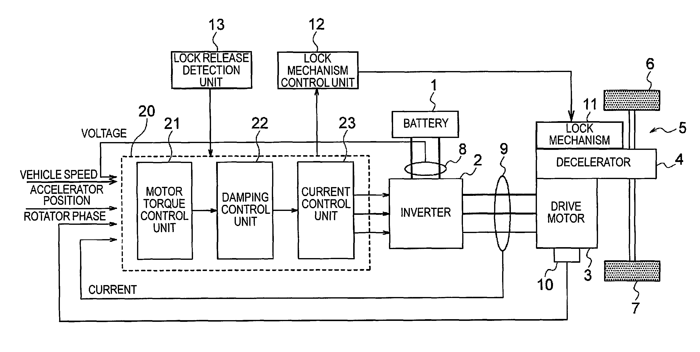
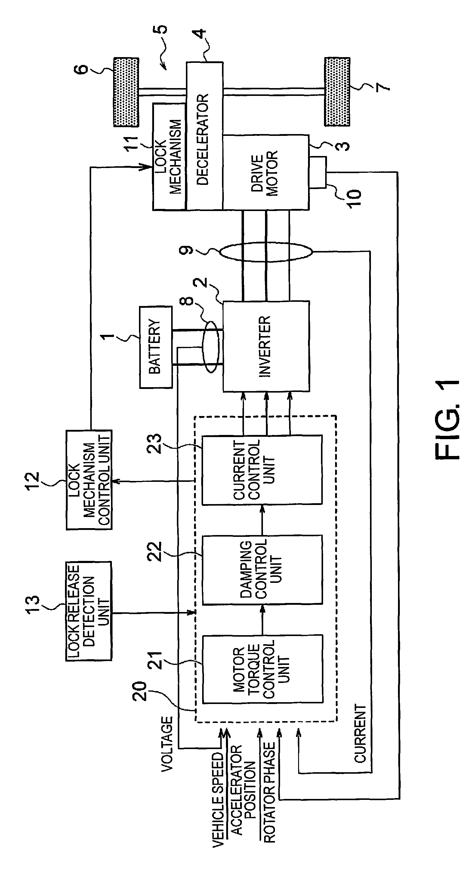
[0023]FIG. 1 is a block diagram showing the configuration of an electric vehicle system equipped with a motor control device according to an embodiment of the present invention. The following description is of an example in which the present motor control device is applied to an electric automobile, but the present motor control device can also be applied to vehicle other than an electric automobile, such as a hybrid automobile (HEV), for example.

[0024]As shown in FIG. 1 a vehicle including the present motor control device comprises a battery 1, an inverter 2, a drive motor 3, a decelerator 4, a drive shaft 5, vehicle wheels 6, 7, a voltage sensor 8, a current sensor 9, a rotational speed sensor 10, a lock mechanism 11, a lock mechanism control unit 12, a lock release detection unit 13, and a motor controller 20.

[0025]The battery 1 is the motive power source of the vehicle, and is configured by a plurality of secondary cells connected in series or in parallel. The inverter 2 has a p...

second embodiment

[0176]FIG. 9 is a block diagram showing the configuration of an electric vehicle system equipped with a motor control device according to another embodiment of the present invention. The present example differs from the first embodiment described above in the configuration of the drive motor 3 and in that a converter 40 is provided. The configuration is otherwise the same as the first embodiment described above, and the statements thereof are incorporated as appropriate.

[0177]The drive motor 3 is a winding field motor, comprising a rotor 31 and a stator 32. The drive motor 3 is driven by rotor current supplied from the converter 40 to the rotor 31 and stator AC current supplied from the inverter 2 to the stator 32.

[0178]The current sensor 9 registers the stator AC current between the inverter 2 and the stator 32 as well as the rotor current between the converter 40 and the rotor 31, and outputs the registered values to the motor controller 20.

[0179]The converter 40, which is part of...


PUM


Abstract

A motor control device of a vehicle includes a motor and a lock mechanism for locking the rotation of vehicle wheels. The motor control device includes a detection device for detecting release of the lock mechanism, a damping control device for suppressing torsional vibration of a drive shaft, and a current control device for controlling current flowing to the motor on the basis of a motor torque command value set by the damping control device. The current control device channels an excitation current for generating a magnetic flux in the motor on the basis of the detection result of the detection device.

Description

CROSS-REFERENCE TO RELATED APPLICATIONS[0001]This application is a U.S. National stage application of International Application No. PCT / JP2013 / 082017, filed Nov. 28, 2013, which claims priority to JP Patent Application No. 2012-287899 filed on Dec. 28, 2012, the contents of each of which are hereby incorporated herein by reference.BACKGROUND[0002]1. Field of the Invention[0003]The present invention relates to a motor control device and a motor control method.[0004]2. Background Information[0005]Japanese Laid-Open Patent Application No. 8-154305 discloses a method for controlling an induction motor, in which a magnetic flux command Φref is set to a synchronous magnetic flux Φs equal to about 25% of a rated value in areas in which a torque command Tref belongs to a range of 0 to tr1, and when the torque command is approximately 0, the magnetic flux command is decided so as to yield a synchronous magnetic flux that enables asynchronous input, thereby improving the responsiveness of the...

Claims


Application Information

Patent Timeline
Patent Type & Authority Patents(United States)
IPC IPC(8): G05B5/01B60L15/20H02P27/06H02P21/05B60T1/00B60W10/00
CPCH02P27/06B60L15/20B60L15/2072B60T1/005B60W10/00H02P21/05B60L2220/12B60L2240/421B60L2240/423B60L2240/429B60L2240/461B60L2240/465B60L2240/547B60L2260/26B60L2270/145Y02T10/643Y02T10/645Y02T10/7275B60L15/2081H02P1/00Y02T10/64Y02T10/72
Inventor KATSUMATA, YUJIITO, KENNAKAJIMA, TAKASHISAWADA, AKIRAOONO, SHOUKOMATSU, HIROYUKI
Owner NISSAN MOTOR CO LTD
Why Eureka
Try Eureka