Centrifugal pendulum damper

a technology of centrifugal pendulum and damper, which is applied in the direction of spring/damper, vibration suppression adjustment, mechanical equipment, etc., can solve the problems of reducing the efficiency of centrifugal pendulum dampers. , to achieve the effect of reducing the torsional vibration, stably suppressing the torsional vibration

Active Publication Date: 2019-02-14
TOYOTA JIDOSHA KK
View PDF8 Cites 12 Cited by
  • Summary
  • Abstract
  • Description
  • Claims
  • Application Information

AI Technical Summary

Benefits of technology

[0006]Aspects of preferred embodiments of the present application have been conceived noting the foregoing technical problems, and it is therefore an object of the present disclosure is to improve vibration damping performance of a centrifugal pendulum damper in which a torque of a prime mover is applied to an inertial mass through a rotary member.
[0012]In the centrifugal pendulum damper according to the embodiment of the present disclosure, when the rotary member is rotated by the torque of the prime mover, the rolling member is centrifugally pushed onto the raceway surface while being oscillated along the raceway surface by torque pulse. According to the embodiment of the present disclosure, the raceway surface is contoured in such a manner that the curvature radius of the orbit of the gravity center of the rolling member is increased with an increase in an oscillation angle of the rolling member. For example, the raceway surface may be contoured such that the orbit of the gravity center of the rolling member takes the form of a part of a parabola, a hyperbolic curve, or an ellipse. According to the embodiment, therefore, an inertial force for suppressing the torque pulse will not be changed in a non-linear fashion or logarithmically with a change in the oscillation angle. Specifically, when the oscillation angle of the rolling member is increased by the torque pulse, the inertial force for suppressing the torque pulse is increased linearly with an increase in the torque pulse. For this reason, the vibration suppressing performance of the centrifugal pendulum damper can be maintained in accordance with a magnitude of the torque pulse. Consequently, the natural frequency of the vibration system can be maintained substantially constant irrespective of the oscillation angle of the rolling member. As a result, the centrifugal pendulum damper is allowed to stably suppress the torsional vibrations of predetermined order.
[0013]A torque transmission point between the rolling member and the inertial member is displaced in the radial direction periodically and repeatedly by a relative rotation between the rotary member and the inertial member caused by the torque pulse. Consequently, the rolling member is oscillated in an opposite phase thereby absorbing the torque pulse transmitted from the rotary member to the inertial member though the rolling member. According to the embodiment, therefore, torsional vibrations resulting from torque pulse can be suppressed and absorbed effectively. In addition, according to the embodiment, the inertial member is arranged concentrically with the rotary member. According to the embodiment, therefore, size and dimension of the inertial member may be altered arbitrarily according to need. For this reason, a large inertial force can be ensured even in a small space to suppress the vibrations effectively.

Problems solved by technology

However, the vibration damping performance of the pendulum damper of this kind may be restricted by a mass of the rolling member.
Therefore, if the oval chamber is described in JP-A-2000-18329 is applied to the centrifugal pendulum damper taught by JP-A-2000-18329, the restoring force may not be changed in a desirable manner and an oscillation width of the inertial ring may not be restricted within a desirable range.

Method used


Image

  • Centrifugal pendulum damper
  • Centrifugal pendulum damper
  • Centrifugal pendulum damper

Examples


Embodiment Construction

)

[0026]Preferred embodiments of the present disclosure will now be explained with reference to the accompanying drawings.

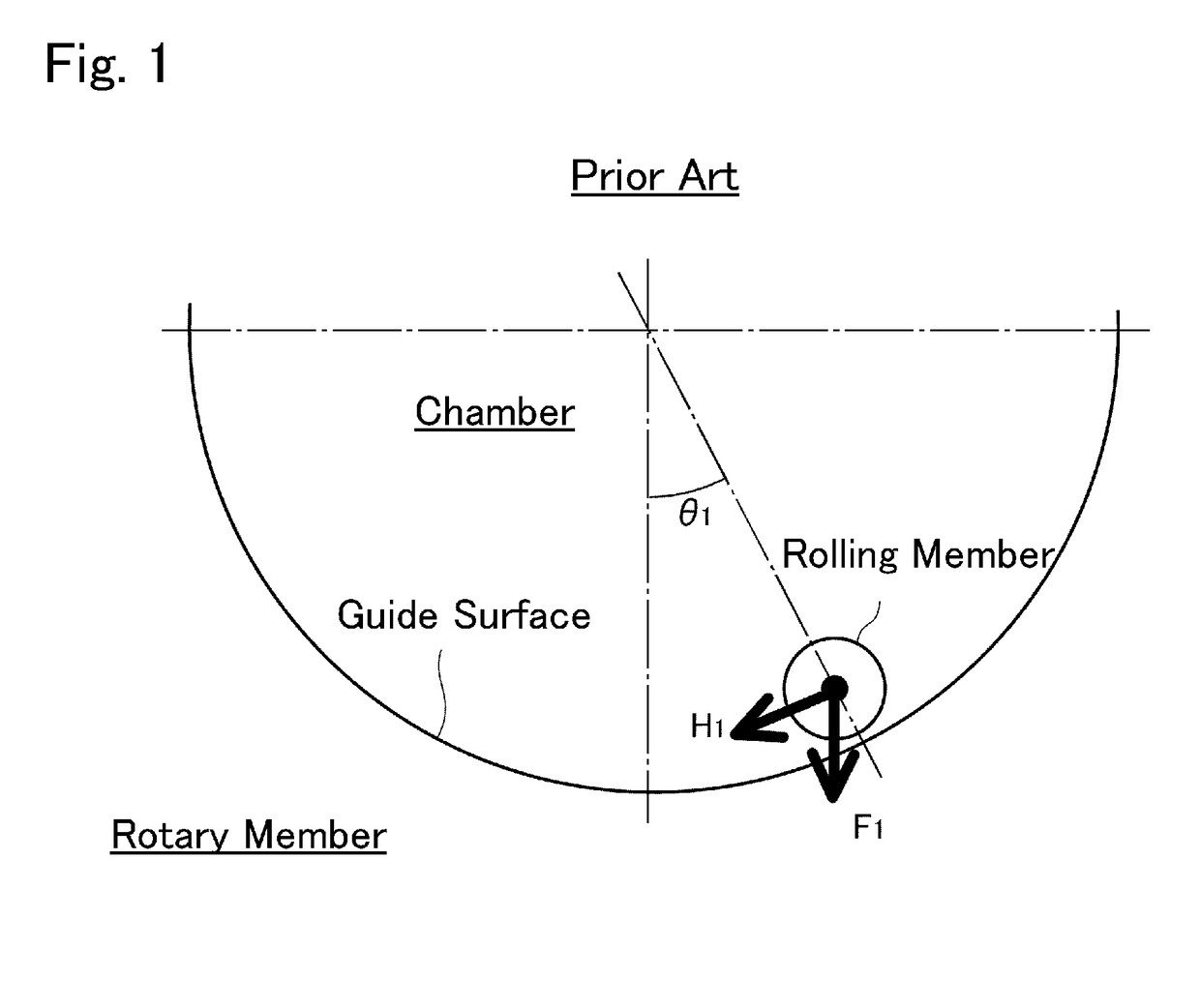
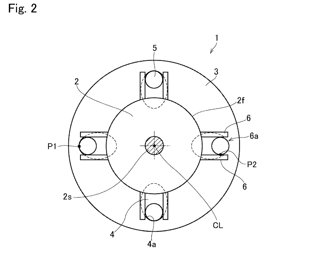
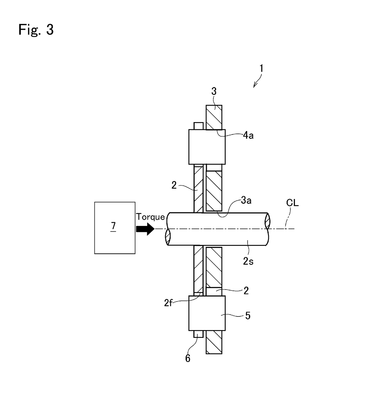
[0027]The present disclosure relates to a centrifugal pendulum damper comprising: a rotary member to which a torque is applied from a prime mover such as an engine; an inertial member that is allowed to rotate relatively to the rotary member; a chamber formed in the inertial member; and a rolling member that is held in the chamber while being allowed to roll along a raceway surface formed on an inner circumferential edge of the chamber. Specifically, the rolling member is held partially in the chamber, and a remaining portion of the rolling member is held by the rotary member while being allowed to move in a radial direction. A torque of the rotary member is transmitted to the inertial member through the rolling member. Consequently, the inertial member is rotated relatively to the rotary member thereby suppressing torsional vibrations on the rotary member. The ap...


PUM


Abstract

A centrifugal pendulum damper for effectively suppressing torsional vibrations resulting from torque pulse. The centrifugal pendulum damper comprises: a rotary member rotated by a torque; an inertial member that rotates relatively to the rotary member; a chamber formed on the inertial member; and a rolling member held partially in the chamber while being allowed to oscillate therein, and held partially by the rotary member while being allowed to move radially. A raceway surface on which the rolling member rolls is formed in the chamber in such a manner that a curvature radius of an orbit of a gravity center of the rolling member oscillating along the raceway surface is increased with an increase in an oscillation angle of the rolling member.

Description

[0001]The present disclosure claims the benefit of Japanese Patent Application No. 2017-153909 filed on Aug. 9, 2017 with the Japanese Patent Office, the disclosure of which is incorporated herein by reference in its entirety.BACKGROUNDField of the Disclosure[0002]The present disclosure relates to the art of a centrifugal pendulum damper for suppressing vibrations resulting from torque pulse.Discussion of the Related Art[0003]JP-A-2000-18329 describes a flywheel having a centrifugal pendulum damper. In the flywheel described in JP-A-2000-18329, chambers individually having a curved guide surface are formed in the main body, and a damper mass (rolling member) is held in each of the chambers. Each of the damper mass is centrifugally pushed onto the guide surface and oscillated by torque pulse along the guide surface thereby absorbing torsional vibrations resulting from pulsation of an engine torque.[0004]In the centrifugal pendulum damper described in Patent JP-A-2000-18329, the guide...

Claims


Application Information

Patent Timeline
Patent Type & Authority Applications(United States)
IPC IPC(8): F16F15/14F16F15/31
CPCF16F15/1457F16F15/31F16F2232/02F16F2222/08F16F15/14
Inventor IWAGAKI, TOMOAMANO, HIROYUKIISHIBASHI, MASAYUKIYONGJOO, RYOO
Owner TOYOTA JIDOSHA KK
Why Eureka
Try Eureka