Eureka AIR delivers breakthrough ideas for toughest innovation challenges, trusted by R&D personnel around the world.

Air-cooling battery module

Active Publication Date: 2019-02-14
LG ENERGY SOLUTION LTD
View PDF3 Cites 2 Cited by
  • Summary
  • Abstract
  • Description
  • Claims
  • Application Information

AI Technical Summary

Benefits of technology

[0021]The air-cooling battery module according to the present disclosure gives the following effects.
[0022]First, since the truss structure is provided in the duct of the cooling member, it is possible to improve the cooling performance and reinforce the mechanical rigidity.
[0023]Second, since a cooling fin may be not used, unlike the conventional

Problems solved by technology

For this reason, it is difficult to simplify the structure and the capacity of cells to be mounted is limited.
However, in this configuration, it is difficult to reduce the weight of the module.
Moreover, a large space is required for installing components in the module, and the space utilization in the thickness direction of the cells is reduced, thereby reducing the capacity and lowerin

Method used


Image

  • Air-cooling battery module
  • Air-cooling battery module
  • Air-cooling battery module

Examples


Example

BEST MODE

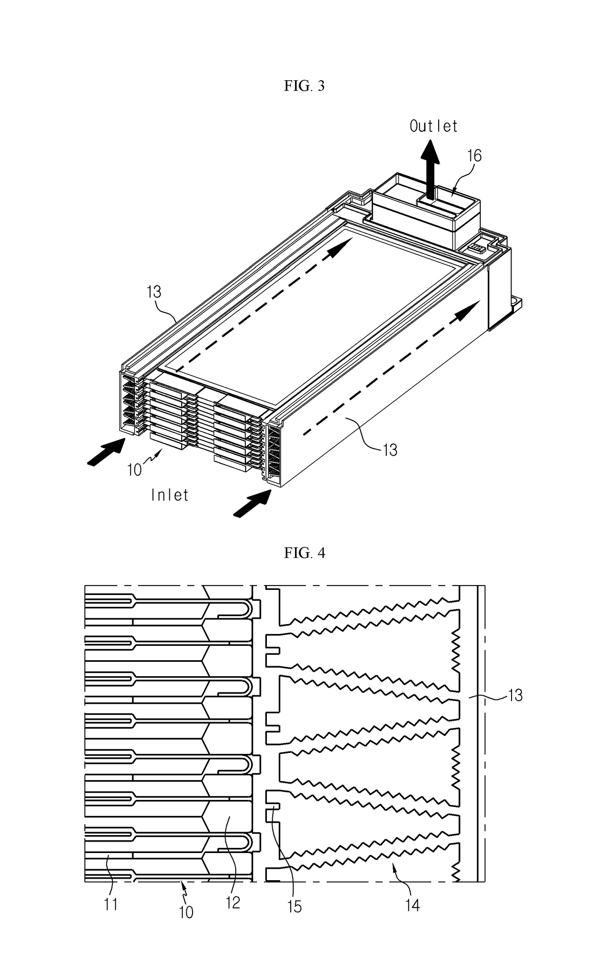
[0032]FIG. 3 is a perspective view showing an appearance of a battery module according to an embodiment of the present disclosure.

[0033]Referring to FIG. 3, a battery module according to an embodiment of the present disclosure includes a cell assembly 10 having a plurality of cells and a cooling member 13 having a duct disposed at both side edge portions of the cell assembly 10.

[0034]Each cell 11 of the cell assembly 10 has a thin plate-like body and preferably has a pouch cell structure. The pouch cell includes a positive electrode, a separator and a negative electrode, which are alternately stacked so that an electrode tab is drawn out from at least one side thereof. The positive electrode and the negative electrode are fabricated by coating slurry containing an electrode active material, a binder resin, a conductive agent and other additives to at least one side of a current collector. In the case of a positive electrode, a common positive electrode active material such ...


PUM


Abstract

Disclosed is an air-cooling battery module, which includes a cell assembly having a plurality of cells and a cooling member having a duct disposed to contact an edge portion of the cell assembly and having an air passage formed therein so that a cooling air moves therethrough, wherein the inside of the duct has a truss structure.

Description

TECHNICAL FIELD[0001]The present application claims priority to Korean Patent Application No. 10-2016-0160635 filed on Nov. 29, 2016 in the Republic of Korea, the disclosures of which are incorporated herein by reference.[0002]The present disclosure relates to an air-cooling battery module, and more particularly, to a battery module having a structure capable of cooling cells by using an air.BACKGROUND ART[0003]Generally, a battery module includes a plurality of cells aggregated by serial and / or parallel connections. The battery module typically includes a cell assembly having a plurality of cells arranged in one direction and a frame having a plate capable of surrounding the cell assembly.[0004]In a conventional battery module, if a cooling channel is separately designed in an air cooling type for cooling battery cells, the space occupied by the cooling channel is separately required. For this reason, it is difficult to simplify the structure and the capacity of cells to be mounted...

Claims


Application Information

Patent Timeline
IPC IPC(8): H01M10/6566H01M10/6556H01M10/6563H01M10/613H01M50/211H01M50/224H01M50/233H01M50/293
CPCH01M10/6566H01M10/6556H01M10/6563H01M10/613H01M10/647H01M10/6551H01M10/6554Y02E60/10H01M50/293H01M50/224H01M50/233H01M50/211H01M10/653H01M50/258H01M50/209
Inventor LEE, JUNG-HOONSHIN, EUN-GYUJEONG, BYOUNG-CHEONKANG, DAL-MOMUN, JEONG-O
Owner LG ENERGY SOLUTION LTD
Why Eureka
Eureka Blog
Learn More