Methods for Reducing Interference in a Wireless Communications Network

Active Publication Date: 2019-02-14
TELEFON AB LM ERICSSON (PUBL)
View PDF1 Cites 5 Cited by
  • Summary
  • Abstract
  • Description
  • Claims
  • Application Information

AI Technical Summary

Benefits of technology

The patent describes a method to improve wireless network performance by reducing interference between signals. This is done by identifying the timing of interference based on the reception of transmitted signals. The information is conveyed to the transmitting node and / or interfering node to adjust their spatial reuse parameters and reduce interference. This results in less data packet loss and improved network efficiency without generating high levels of interference. Overall, the patent aims to enhance transmission performance in wireless networks.

Problems solved by technology
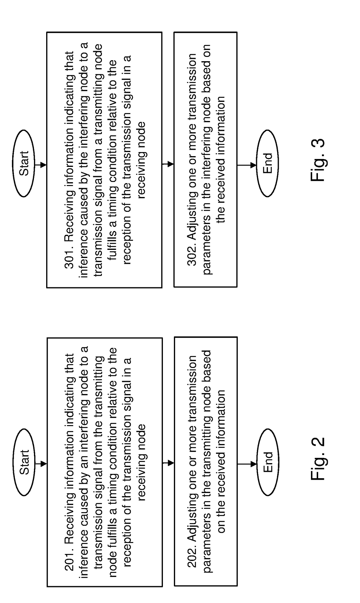
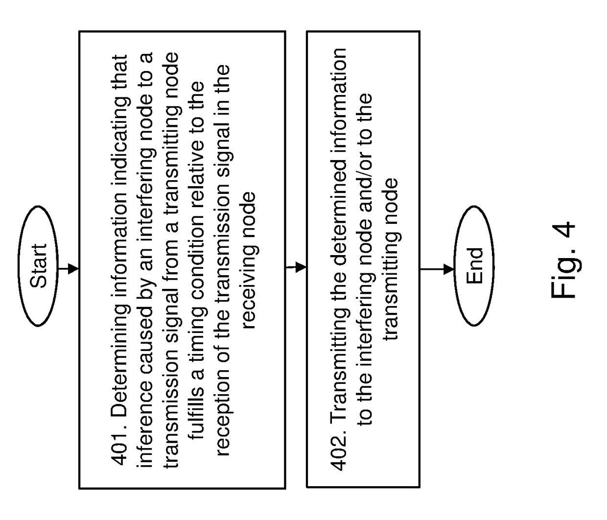
This has the disadvantage of limiting the number of simultaneous transmissions that may be performed in the BSS / OBSS at any given time.
In turn, this will also limit the performance of the wireless communications network by not fully utilizing the available channel; especially, as the CCAT used today is conservatively set to the very low value, such as, e.g. −82 dBm.
However, while spatial reuse features in the WLAN may improve efficiency of the wireless communications network, it will also increase the interference level in the entire wireless communications network.
Such time dynamic interferences brings challenges to the design of link adaptation and may cause high packet loss rate if the link adaptation fails to adjust the Modulation and Coding Scheme, MCS, according to the level of the interference.
Consequently, this high packet loss rate may result in both reduced user throughput and higher transmission latency, which leads to a decrease in transmission performance in the wireless communications network.

Method used


Image

  • Methods for Reducing Interference in a Wireless Communications Network
  • Methods for Reducing Interference in a Wireless Communications Network
  • Methods for Reducing Interference in a Wireless Communications Network

Examples


Embodiment Construction

[0028]The figures are schematic and simplified for clarity, and they merely show details which are essential to the understanding of the embodiments presented herein, while other details have been left out. Throughout, the same reference numerals are used for identical or corresponding parts or steps.

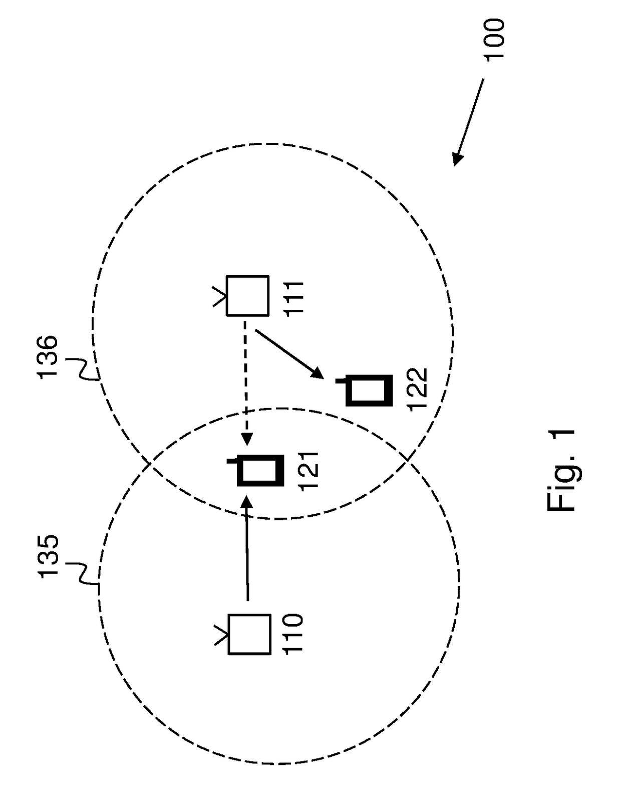
[0029]FIG. 1 shows an example of a wireless communications network 100 in which embodiments herein may be implemented. The wireless communications network 100 in

[0030]FIG. 1 comprise two Wireless Local Area Networks, WLANs, i.e. a first WLAN 135 and a second WLAN 136. It should be noted that this is for illustrative purposes only, and that any number of WLANs may be comprised in the wireless communications network 100.

[0031]The first and second WLAN 135, 136 each comprise one or more Access Points, APs, configured to provide WLAN coverage and serve stations, STAs, located within their respective coverage area or cell. For example, the first WLAN 135 may comprise a first AP 110 and the s...


PUM


Abstract

A method performed by a transmitting node (110) for reducing interference in a wireless communications network (100) is provided. The transmitting node (110) receives information indicating that inference caused by an interfering node (111) to a transmission signal from the transmitting node (110) fulfills a timing condition relative to the reception of 5 the transmission signal in a receiving node (121) in the wireless communications network (100). Then, the transmitting node (110) adjusts one or more transmission parameters in the transmitting node (110) based on the received information. A transmitting node (110) is also provided. Furthermore, an interfering node (111) and a method therein for reducing 10 interference in a wireless communications network (100) are also provided, as well as, a receiving node (121) and a method therein for reducing interference in a wireless communications network (100).

Description

TECHNICAL FIELD[0001]Embodiments herein relate to reducing interference in a wireless communications network. In particular, embodiments herein relate to a transmitting node and method therein for reducing interference in a wireless communications network, as well as, a interfering node and method therein for reducing interference in a wireless communications network. Embodiments herein further relate to a receiving node and method therein for reducing interference in a wireless communications network.BACKGROUND[0002]The standardized IEEE 802.11 Wireless LAN, WLAN, also referred to as a Wi-Fi network, is a wireless communications network technology that operates on unlicensed frequency bands. Currently, the standardized IEEE 802.11 WLAN operate mainly on the 2.4 GHz and / or the 5 GHz band. The standard specifications regulate the Physical, PHY, layer, Medium Access Control, MAC, layer, and other aspects of the nodes therein to secure their compatibility and inter-operability.[0003]In...

Claims


Application Information

Patent Timeline
IPC IPC(8): H04W16/14H04W16/10H04W52/14H04W52/24H04W74/08H04W72/12
CPCH04W16/14H04W16/10H04W52/143H04W52/243H04W52/247H04W74/0816H04W84/12H04W80/02
Inventor WANG, YUBERGSTROM, ANDREASMESTANOV, FILIPTAYAMON, SOMA
Owner TELEFON AB LM ERICSSON (PUBL)
Why Eureka
Try Eureka