
Vehicle Control Device and Method

a technology of vehicle control and mounting portion, which is applied in the direction of driver input parameters, brake systems, transportation and packaging, etc., can solve the problems of limited controllability, unnatural and uncomfortable steering feeling, and difficulty in ensuring the rigidity of the mounting portion, so as to improve the apparent rigidity of the steering mechanism, improve the steering feeling, and improve the effect of steering accuracy

Active Publication Date: 2019-02-21
HITACHI ASTEMO LTD
View PDF9 Cites 25 Cited by
  • Summary
  • Abstract
  • Description
  • Claims
  • Application Information

AI Technical Summary

Benefits of technology

The present invention controls the steering force or reaction force to improve the steering feeling and make the steering mechanism appear stiffer, thus improving the steering accuracy. The technical effect of this invention is to enhance the overall steering experience of the vehicle.

Problems solved by technology

Contrary to the hydraulic power steering that amplifies a force by applying hydraulic pressure to a cylinder integrated with a steering rack by an action of a hydraulic circuit, in the electric power steering, control is performed by a motor that outputs according to a calculation result of a feedback of information of a steering torque sensor, and increase in friction and inertia due to addition of a motor and a deceleration mechanism of the motor cannot be avoided, which results in limitation of controllability.
Particularly, in an inexpensive electric power steering for which a large budget cannot be allowed for reduction of tooth surface friction of a deceleration mechanism, weight reduction of a movable portion, improvement of responsiveness of a motor, or the like, there may be unnaturalness and discomfort in steering feeling.
In particular, in a column electric power steering, it is difficult to secure the rigidity of a mounting portion as compared with a rack type or a dual pinion type that receives a reaction force of power steering with a steering rack, and the mechanism also receives the reaction force in a position far from the wheel (tire) via a column axis.
Therefore, the amount of deformation of the mounting portion and the steering mechanism increases with respect to a steering force of the same degree of steering force, and an extent of decreasing of the apparent rigidity is large.
Since this hinders correct steering, there is still room for improvement in the control of the steering force.

Method used


Image

  • Vehicle Control Device and Method
  • Vehicle Control Device and Method
  • Vehicle Control Device and Method

Examples


first embodiment

[0035]In the present embodiment, the case where a steering wheel torque (steering reaction force) imparted to a driver who steers a vehicle via a steering wheel is controlled by a braking force will be described.

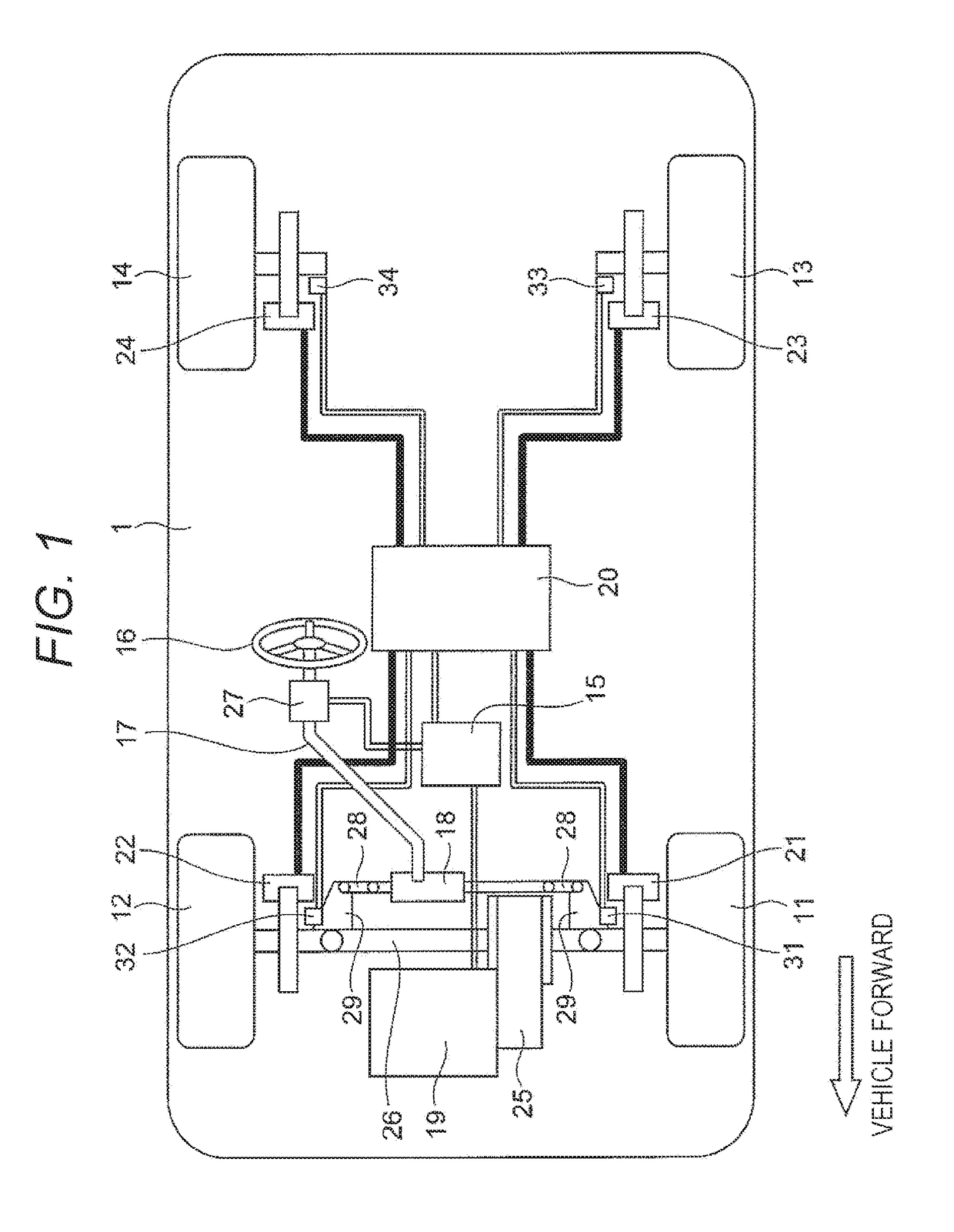
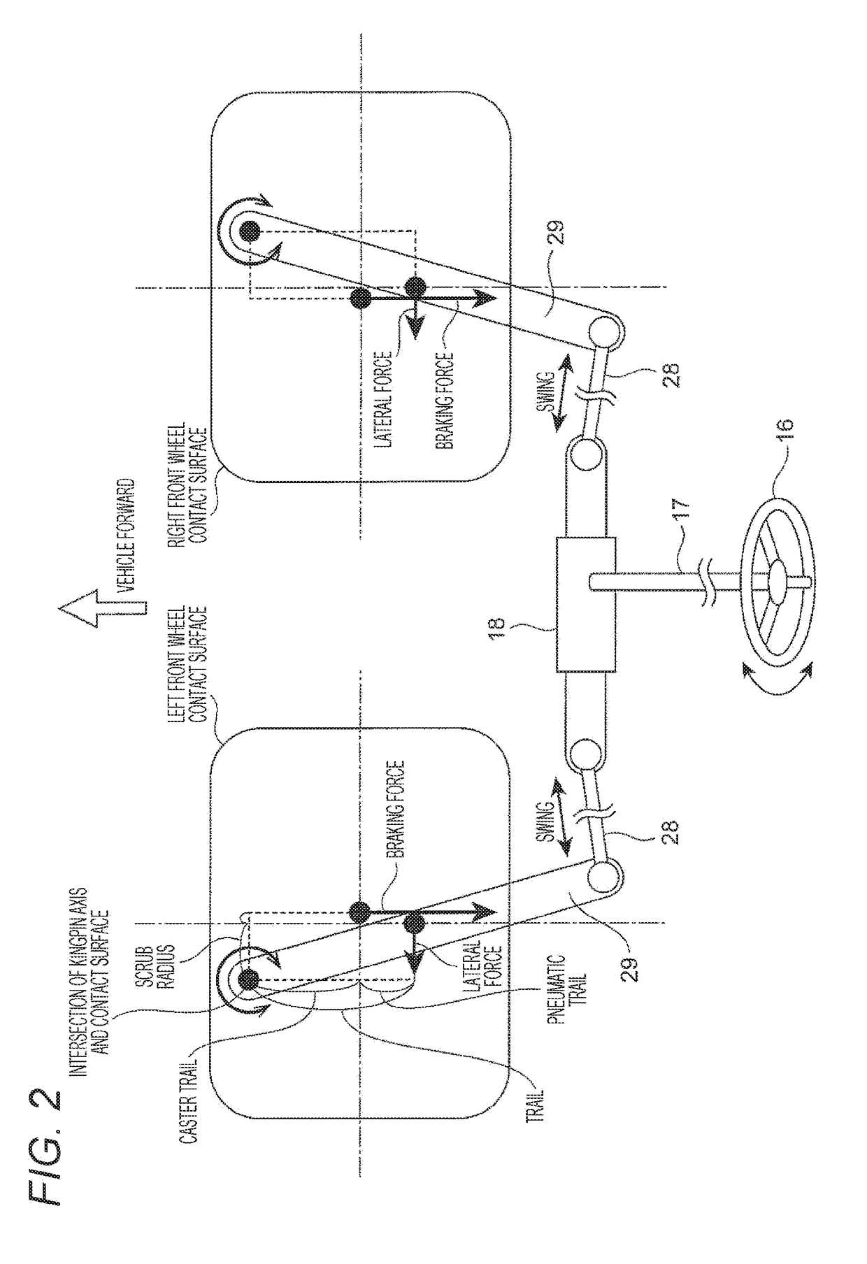
[0036]FIG. 1 shows a system configuration of a mechanism and a control system of a vehicle 1 in which braking forces of four wheels (left front wheel 11, right front wheel 12, left rear wheel 13, right rear wheel 14) can be independently controlled, and the front wheels 11, 12 are steered wheels (wheels of which steering angle can be controlled by a steering mechanism). A steering wheel 16 and the front wheels 11, 12 are coupled with each other via a steering column shaft 17, a steering rack 18, a steering tie rod 28, a steering knuckle 29, and the like such that the steering power (steering force) can be transmitted between the steering wheel 16 operated by the driver and the front wheels 11, 12 that are the steered wheels. An electric power steering device 27 provided on t...

second embodiment

[0100]In the present embodiment, the case where a steering wheel torque (steering reaction force) imparted to a driver is controlled by a braking force and a driving force will be described. The difference from the first embodiment is steering wheel torque control in a vehicle in which not only the control force but also the driving force of the steered wheels (here, the left front wheel 11 and the right front wheel 12) can be controlled independently for left and right. Other configurations are substantially the same as those of the first embodiment. Therefore, the same reference numerals are given to the same configurations as those of the first embodiment, and the detailed description thereof will be omitted, and only the differences will be described in detail below.

[0101]FIG. 10 shows the system configuration of the mechanism and the control system of the vehicle having motors that drive the right and left front wheels independently. The difference from the system configuration...

third embodiment

[0107]In the present embodiment, the case where the steering force of the steering force generation device is controlled by the braking / driving forces in a vehicle having an automatic steering function that does not require steering wheel operation by a driver will be described.

[0108]The system configuration of the vehicle in the present embodiment is substantially the same as the system configuration of the vehicle of the first or second embodiment shown in FIG. 1 or FIG. 10, but here, the driver does not hold (operate) the steering wheel 16, so that only the electric power steering device 27 serves as a steering force generation device (see FIG. 1 or FIG. 10).

[0109]Unlike the first and second embodiments, in the present embodiment, since the driver does not hold the steering wheel 16, the steering wheel torque is not defined. In automatic steering that is angle control, friction feeling and inertia feeling do not impair the steering accuracy. However, since all of the steering for...


PUM


Abstract

The present invention provides a vehicle control device and method capable of ensuring steering accuracy. In a vehicle provided with a left-right pair of steered wheels for which the braking / driving forces can each be controlled, and a steering force generation device that generates steering force for the steered wheels and controls the steering angle of the steered wheels, this vehicle control device and method control the steering force and the steering reaction force from the steering force generation device by controlling the braking / driving force of each of the steered wheels on the basis of the lateral force acting on the steered wheels.

Description

TECHNICAL FIELD[0001]The present invention relates to a vehicle control device and a method, and in particular to a vehicle control device and a method for controlling a steering force or a steering reaction force of a steering force generation device disposed in a vehicle such as an automobile.BACKGROUND ART[0002]In a steering device of a vehicle such as a passenger car, an electric power steering is excellent in energy saving, and it is advantageous in that not only a boosting function but also an assisting function of actively steering and an automatic steering function can be incorporated by control. Thus, an electric power steering is a recent major power steering system.[0003]Contrary to the hydraulic power steering that amplifies a force by applying hydraulic pressure to a cylinder integrated with a steering rack by an action of a hydraulic circuit, in the electric power steering, control is performed by a motor that outputs according to a calculation result of a feedback of ...

Claims


Application Information

Patent Timeline
Patent Type & Authority Applications(United States)
IPC IPC(8): B60W30/045B60W10/20B60W10/188B60W10/22B60W30/12B60G17/016B60G17/0195B62D6/00
CPCB60W30/045B60W10/20B60W10/188B60W10/22B60W30/12B60G17/0162B60G17/0195B62D6/00B60W2710/207B60W2710/18B60W2710/22B60W2540/18B60W2520/10B60W2520/125B60W2520/14B60G17/016B60T8/00B62D5/006B62D5/008B62D5/0409B62D5/0463B62D6/002B62D6/003B62D6/04B62D7/146B60W2710/182Y02T10/72B60W2720/30B60W10/08B60W10/18B60W10/04B60W10/00
Inventor AKIYAMA, YUKITAKAHASHI, JUNYAINNAMI, TOSHIYUKI
Owner HITACHI ASTEMO LTD
Learn More