

Smart-home device switching circuitry with integrated power stealing control
a smart-home device and integrated power theft technology, applied in the direction of program control, heating types, instruments, etc., can solve the problems of blown fuse, incorrect connection of wires, and permanent damage to either the thermostat, hvac wiring and/or other hvac system components
- Summary
- Abstract
- Description
- Claims
- Application Information
AI Technical Summary
Benefits of technology
Problems solved by technology
Method used
Image

Examples
Embodiment Construction
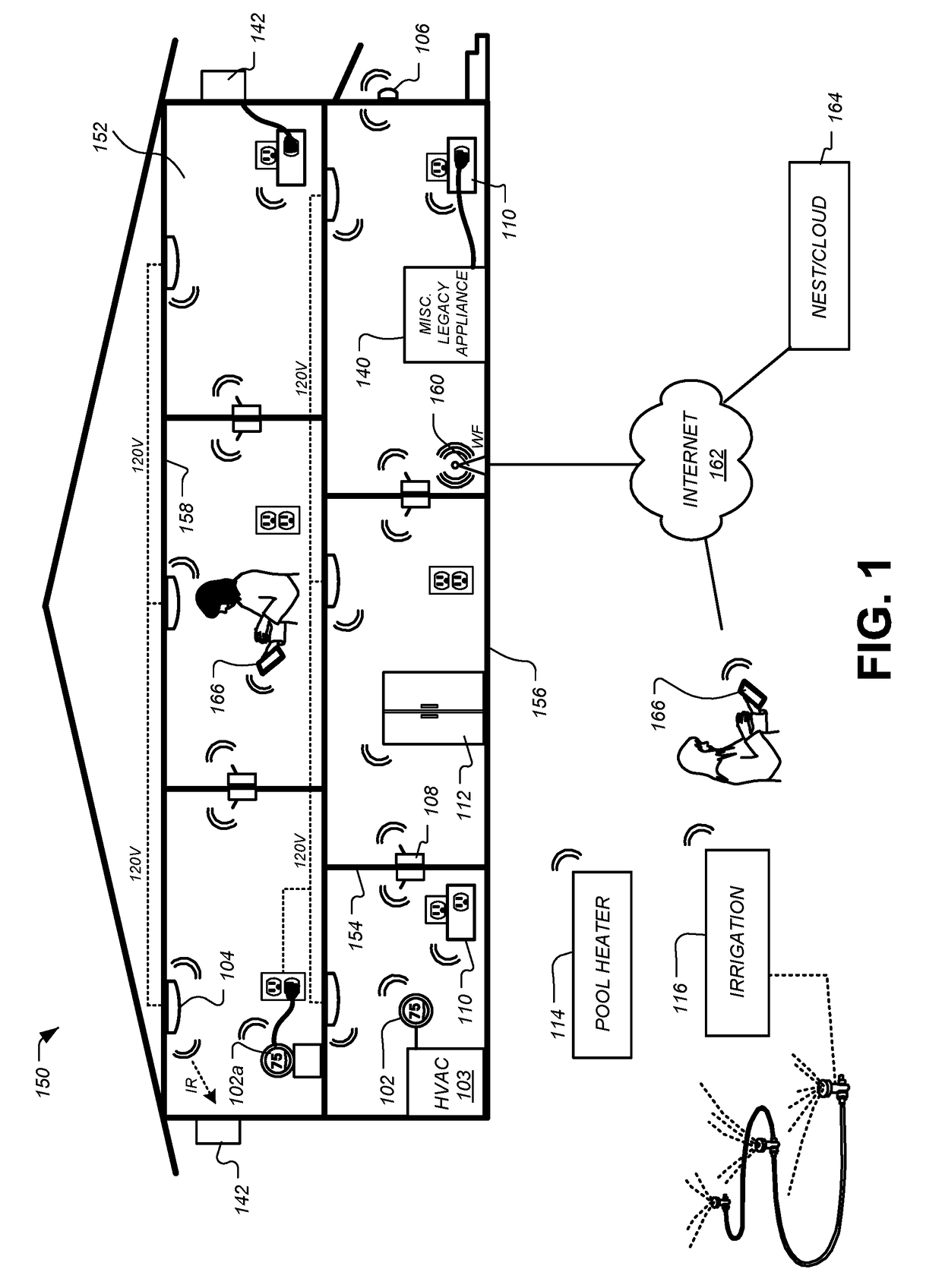
The Smart-Home Environment
[0037]A detailed description of the inventive body of work is provided herein. While several embodiments are described, it should be understood that the inventive body of work is not limited to any one embodiment, but instead encompasses numerous alternatives, modifications, and equivalents. In addition, while numerous specific details are set forth in the following description in order to provide a thorough understanding of the inventive body of work, some embodiments can be practiced without some or all of these details. Moreover, for the purpose of clarity, certain technical material that is known in the related art has not been described in detail in order to avoid unnecessarily obscuring the inventive body of work.
[0038]As used herein the term “HVAC” includes systems providing both heating and cooling, heating only, cooling only, as well as systems that provide other occupant comfort and / or conditioning functionality such as humidification, dehumidific...
PUM
 Abstract
Description
Claims
Application Information