Cutting insert and cutting tool

a cutting tool and cutting insert technology, applied in the field of cutting inserts and cutting tools, can solve the problems of reducing the product life of the cutting insert, prone to chipping of the cutting insert during machining, etc., and achieve the effect of small cutting load, reduced manufacturing costs, and reduced manufacturing costs

Active Publication Date: 2019-02-28
TUNGALOY CORP
View PDF5 Cites 2 Cited by
  • Summary
  • Abstract
  • Description
  • Claims
  • Application Information

AI Technical Summary

Benefits of technology

[0012]The width of the honing of the inner cutting edge, as viewed from the side of the end surface, may gradually become narrower as a distance thereof from a connecting part connected to the end cutting edge increases. Since the inner cutting edge is subjected to a smaller cutting load as the distance from a connecting part connected to the end cutting edge increases, according to this aspect, the width of honing decrease

Problems solved by technology

In such a cutting tool, when a cutting edge of the cutting insert is pointed, the cutting insert is susceptible to chipping during machining.
In this case,

Method used


Image

  • Cutting insert and cutting tool
  • Cutting insert and cutting tool
  • Cutting insert and cutting tool

Examples


Embodiment Construction

[0027]Hereinafter, a preferred embodiment of the present invention will be described with reference to the drawings. Note that same elements will be denoted by same reference characters and redundant descriptions will be omitted. Unless otherwise noted, positional relationships such as up, down, left, and right are to be based on positional relationships depicted in the drawings. In addition, dimensional ratios in the drawings are not limited to the depicted ratios. Furthermore, it is to be understood that the embodiment described below is for illustrative purposes only and is not intended to limit the present invention thereto.

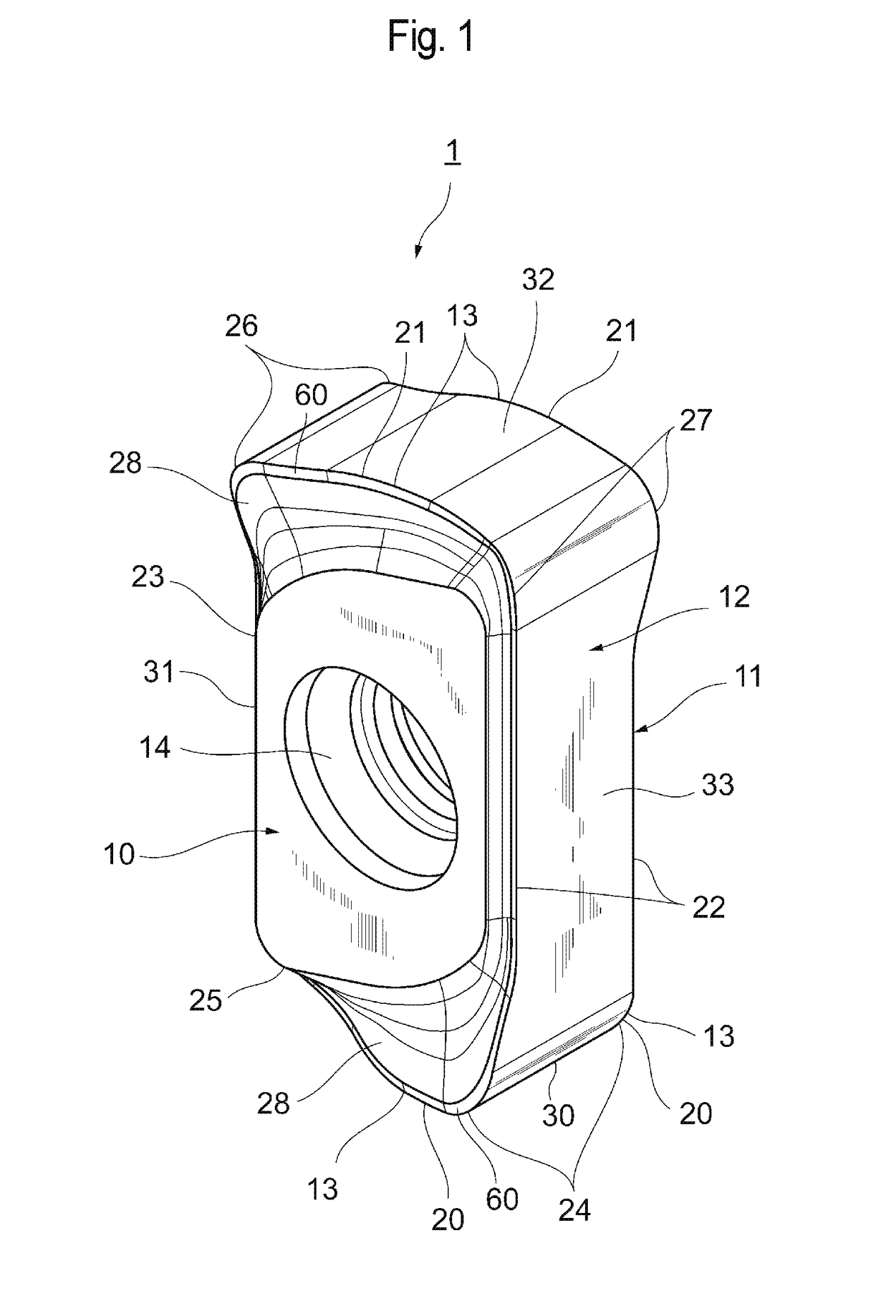
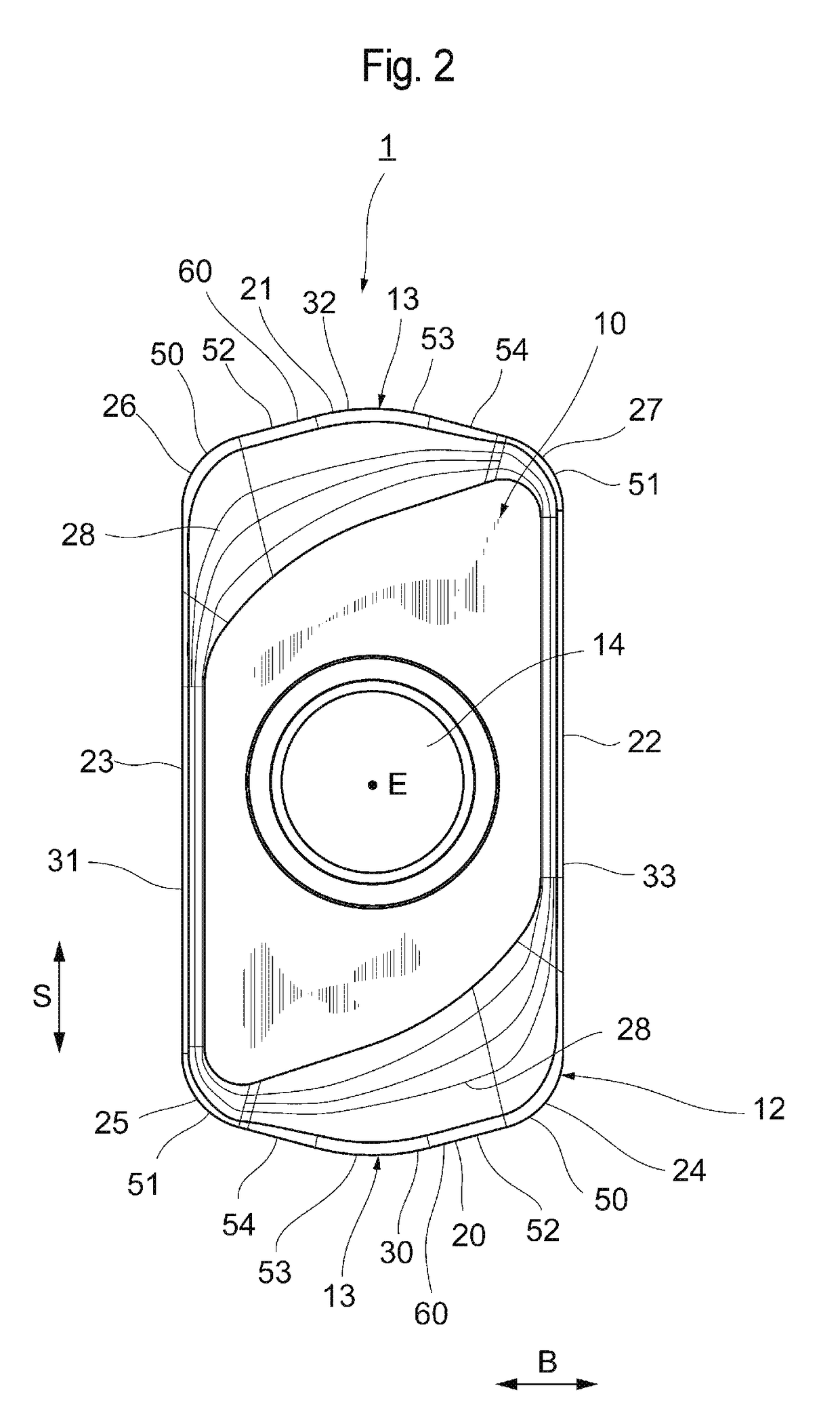
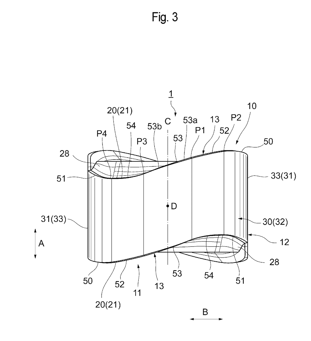
[0028]FIG. 1 is a perspective view of a cutting insert 1 according to the present embodiment, and FIG. 2 is a front view of the cutting insert 1 as viewed from a side of an end surface. FIG. 3 is a side view of the cutting insert 1 as viewed from a side of a peripheral side surface.

[0029]The cutting insert 1 is for, for example, an end mill suitable for high-...


PUM

PropertyMeasurementUnit
Widthaaaaaaaaaa
Widthaaaaaaaaaa

Abstract

The present invention provides a cutting insert in which suitable honing is formed on a cutting edge. The cutting insert is provided with: two end surfaces opposing each other; a peripheral side surface extending between the two end surfaces; and a cutting edge formed on an intersecting ridge between at least one of the two end surfaces and the peripheral side surface. The cutting edge at least includes a major cutting edge and an inner cutting edge. Honing is provided on the major cutting edge and the inner cutting edge. A width of second honing of the inner cutting edge is narrower than a width of first honing of the major cutting edge, as viewed from a side of the end surfaces.

Description

BACKGROUNDField[0001]The present invention relates to a cutting insert and a cutting tool.Description of Related Art[0002]In cutting processes of a mold and the like, for example, an indexable end mill is used as a cutting tool. A cutting tool of this type is provided with a tool body having an approximately columnar shape and a cutting insert mounted to a leading end part of the tool body in an axial direction.[0003]In such a cutting tool, when a cutting edge of the cutting insert is pointed, the cutting insert is susceptible to chipping during machining. Therefore, fracture resistance is increased by subjecting the cutting edge to a process of making the edge less pointed (honing). Honing includes rounding, chamfering, and a combination thereof (refer to WO 2017 / 073590).SUMMARY[0004]Some cutting inserts are provided with a so-called inner cutting edge on an inner side of a major cutting edge in order to accommodate ramping in which a cutting tool is moved diagonally downward, plun...

Claims


Application Information

Patent Timeline
IPC IPC(8): B23C5/20B23C5/22
CPCB23C5/207B23C5/223B23C2200/0461B23C2200/123B23C2200/203B23C2200/246B23C2200/361B23C2210/203B23C2222/28B23C5/109B23C5/20B23C2200/326B23C2200/0416B23C2200/085B23C2200/243B23C5/202B23C5/2226
Inventor SHIROMA, HIKARU
Owner TUNGALOY CORP
Why Eureka
Try Eureka