Multifunctional turning blade integrating coarse machining with fine machining and cutting tool
A technology for multi-functional vehicles and cutting tools, applied to cutting blades, tools for lathes, turning equipment, etc., can solve the problems of limited cutting efficiency, poor economy, poor clamping stability, etc., to improve the quality of the machined surface, cutting High efficiency and low cutting load
- Summary
- Abstract
- Description
- Claims
- Application Information
AI Technical Summary
Problems solved by technology
Method used
Image
Examples
Embodiment 1
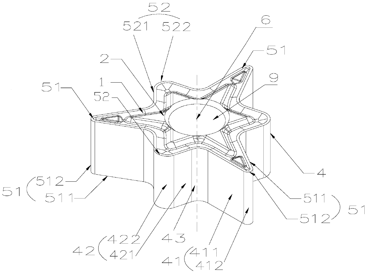
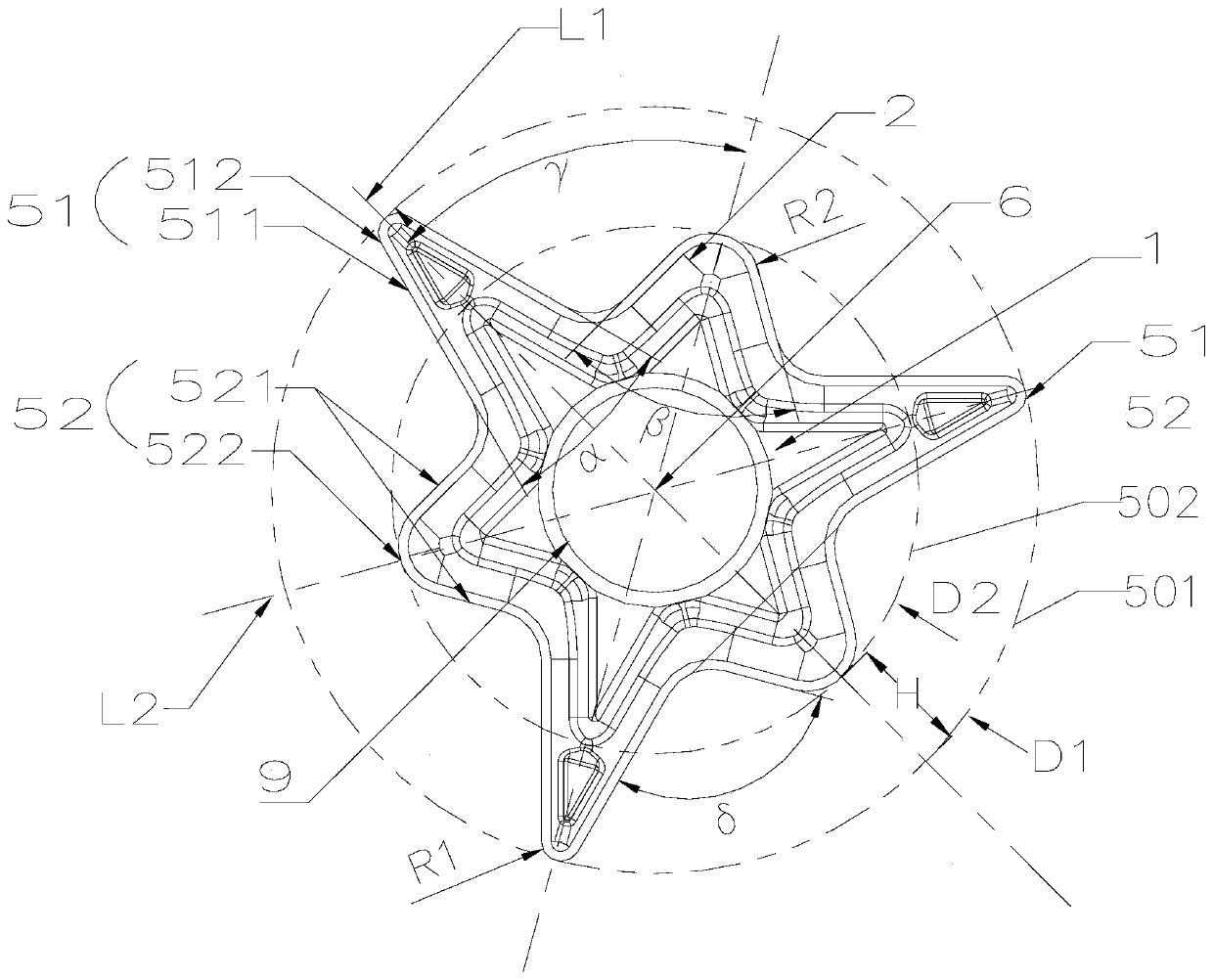
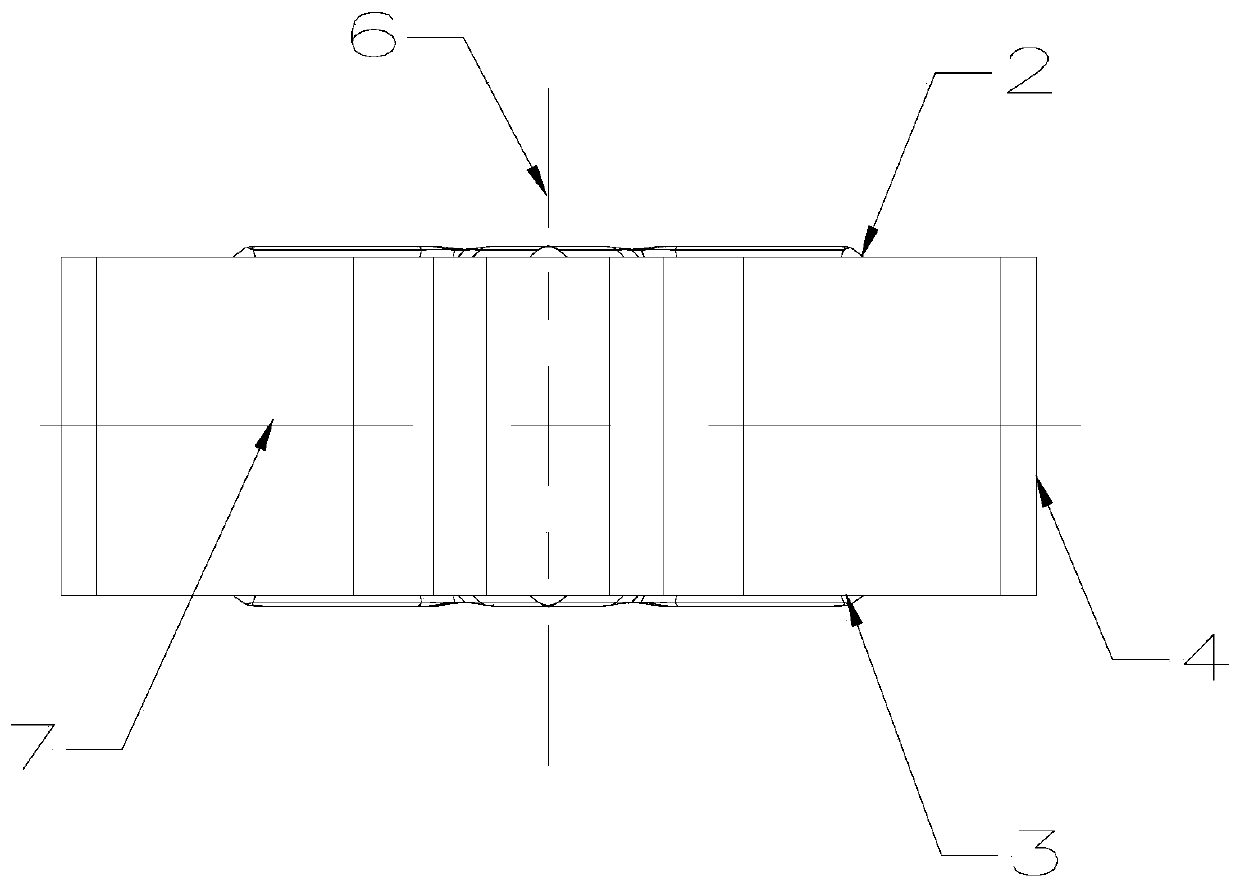
[0038] Such as Figure 1 to Figure 5 As shown, the multifunctional turning insert with integrated roughing and finishing in this embodiment includes an insert body 1, the insert body 1 is provided with a corner cutting unit 51 and a core cutting unit 52, and the corner cutting unit 51 protrudes relative to the core cutting unit 52 The distance is H, H>0, the diameter of the corner circumscribed circle 501 of the corner cutting unit 51 is D1, the diameter of the core circumscribed circle 502 of the core cutting unit 52 is D2, H=(D1-D2) / 2. That is, because the lengths of the protruding parts of the corner cutting unit 51 and the core cutting unit 52 are inconsistent, they will contact the workpiece successively during cutting, so that the cutting areas of the corner cutting unit 51 and the core cutting unit 52 are different, and layered cutting can be realized. When turning, if the corner cutting unit 51 is in front, then the corner cutting unit 51 cuts off a small part, and the...
Embodiment 2
[0052] Such as Figure 6 to Figure 8 As shown, the multifunctional turning insert with integrated roughing and finishing of the present embodiment, compared with embodiment 1, differs in that:
[0053] In this embodiment, the blade is not a symmetrical structure up and down. The side 4 is divided into an upper side 45 and a lower side 46, the corner side 41, the core side 42 and the transition side 43 are located on the upper side 45, and only the upper surface 2 has the corner cutting unit 51 and the core cutting unit 52. , in order to ensure that the corner cutting unit 51 and the core cutting unit 52 have the cutting ability, the corner side surface 41 and the core side surface 42 have relief angles λ1 and λ2, 5°≤λ1≤15°, 5°≤λ2≤15°, in this embodiment , preferably, λ1=11°, λ2=7°.
[0054] In this embodiment, the positioning side 8 is on the lower side 46, and the positioning side 8 is formed by the part of the lower side 46 in the area of two adjacent corner cutting unit...
Embodiment 3
[0061] Such as Figure 9 to Figure 11 As shown, the cutting tool of this embodiment also includes the turning insert in the first embodiment above. The cutter body 10 is provided with a sipe 12 , and the turning insert is installed in the sipe 12 and fixed by the fastening assembly 11 .
[0062]A spacer 13 is arranged between the turning insert and the sipe 12, and the side positioning surface 8 is composed of two corner straight faces 411 and two core straight faces 421 between adjacent corner cutting units 51, and the two corner straight faces 411 and two core straight faces 421 and the knife The side surfaces of the groove 12 form a V-shaped side contact with one convex and one concave. The fastening assembly 11 comprises a fastening screw 101 and an L-shaped lever 102. The vertical part of the L-shaped lever 102 is passed through the clamping hole 9 of the blade. It is located in the receiving hole 121 and locked by the elastic piece 14 . The fastening screw 101 is inser...
PUM
 Abstract
Description
Claims
Application Information
 - R&D
- Intellectual Property
- Life Sciences
- Materials
- Tech Scout
- Unparalleled Data Quality
- Higher Quality Content
- 60% Fewer Hallucinations
Browse by: Latest US Patents, China's latest patents, Technical Efficacy Thesaurus, Application Domain, Technology Topic, Popular Technical Reports.
© 2025 PatSnap. All rights reserved.Legal|Privacy policy|Modern Slavery Act Transparency Statement|Sitemap|About US| Contact US: help@patsnap.com


