Heavy current reed switch contact structure

a reed switch and heavy current technology, applied in the field of switch contacts, can solve the problems of arc-extinguishing devices that cannot be installed, switch contacts are burned, and the contact is not adhered to the surface, so as to increase the electric charge carrying ability of magnetic reed switches, reduce the damage of contact surfaces, and increase the electric charge carrying ability of reed switches

Active Publication Date: 2019-02-28
JING DEQIANG +1
View PDF4 Cites 0 Cited by
  • Summary
  • Abstract
  • Description
  • Claims
  • Application Information

AI Technical Summary

Benefits of technology

[0008]Since the transfer time for an electric arc from the surfaces of two contacts to the arc discharge devices at the ends of the two electrodes is extremely short, the continuing combustion of the electric arc happens mostly between the arc discharge devices at the ends of the two electrodes, thus substantially reducing the damage of contact surfaces caused by electr

Problems solved by technology

The electric arc seriously erodes the surfaces of the electric contacts, leading to the adhesion of the electric contacts, and even burning down the switch contacts.
Although these arc-extinguishing methods exhibit good arc-extinguishing effect, for some volume-limited small reed switches with compact structure, the arc-extinguishing devices cannot

Method used


Image

  • Heavy current reed switch contact structure
  • Heavy current reed switch contact structure
  • Heavy current reed switch contact structure

Examples


example 1

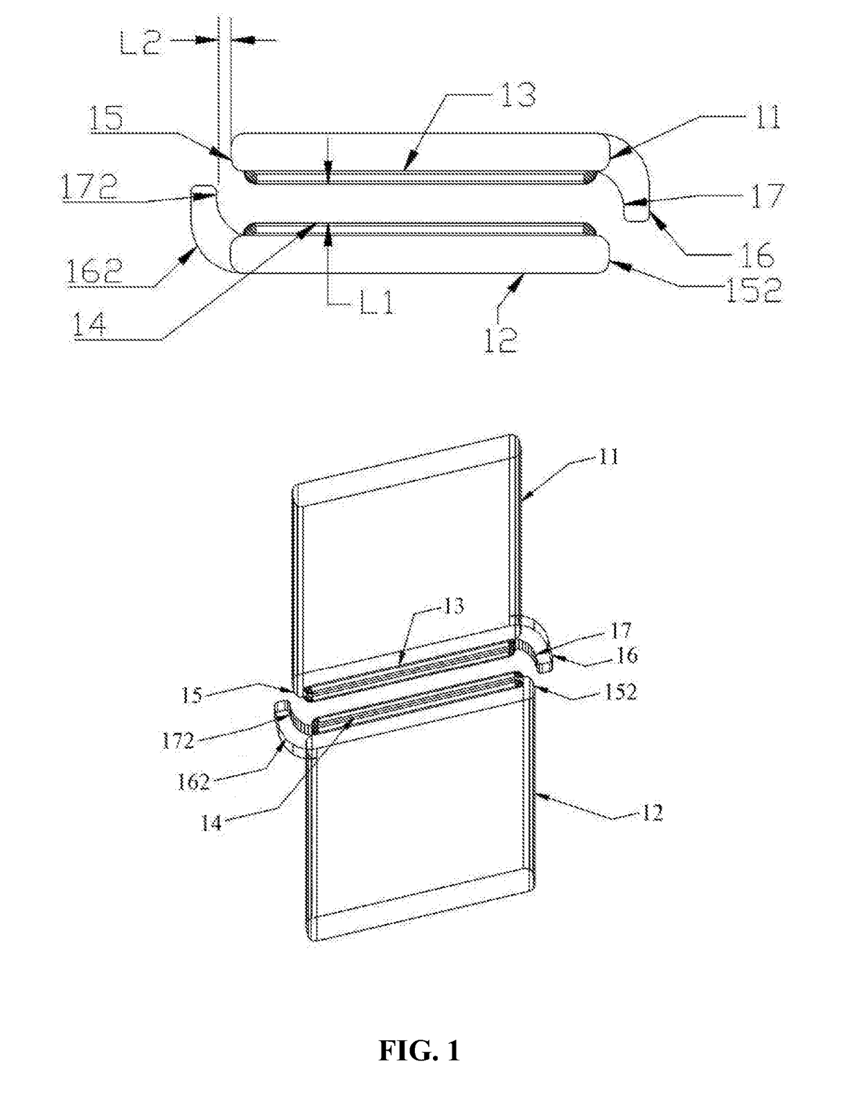
[0017]FIG. 1 shows a heavy current reed switch contact, which is a normally open structure. The reed switch contact comprises at least one pair of elastic reed electrodes (11, 12), or at least one fixed electrode (12) and one elastic reed electrode (11). The electrodes (11, 12) are made of conducting materials and the surfaces of one end of the electrodes overlap. The opposite sides of the overlapped ends comprise contacts (13, 14). The end of the reed electrode (11) in the vicinity of the contacts comprises a first protruding arc discharge device (16). The end of the other reed electrode (12) in the vicinity of the contacts comprises a second protruding arc discharge device (162). There is a gap between the reed electrode contacts (13, 14). The front distance (L1) between the electrode contacts (13, 14) and the distance (L2) between the side shoulders (15, 152) of the contacts and the shoulders (17, 172) of the arc discharge device are determined by relevant working parameters such...

example 2

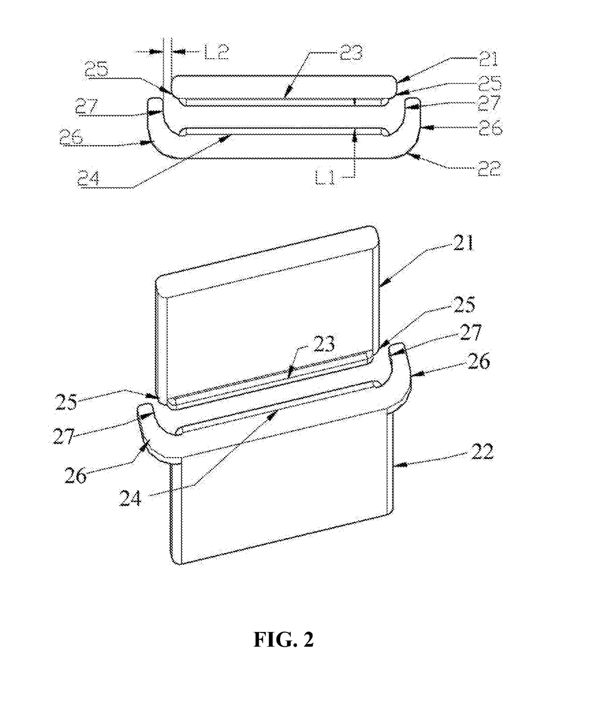
[0020]FIG. 2 shows a heavy current reed switch contact which is a normally open structure. The reed switch contact comprises at least one pair of elastic reed electrodes (21, 22), or at least one fixed electrode (22) and one elastic reed electrode (21). The electrodes (21, 22) are made of conducting materials and the surfaces of one end of the electrodes overlap. The opposite sides of the overlapped ends comprise contracts (23, 24). The end of the reed electrode (22) in the vicinity of the contacts comprises a protruding arc discharge device (26). There is a gap between the reed electrode contacts (23, 24). The front distance (L1) between the electrode contacts (23, 24) and the distance (L2) between the side shoulder (25) of the contact and the shoulder (27) of the arc discharge device are determined by relevant working parameters such as the specific breaking current and voltage and breakdown voltage. The front distance (L1) between contacts in a static break state is larger than t...

example 3

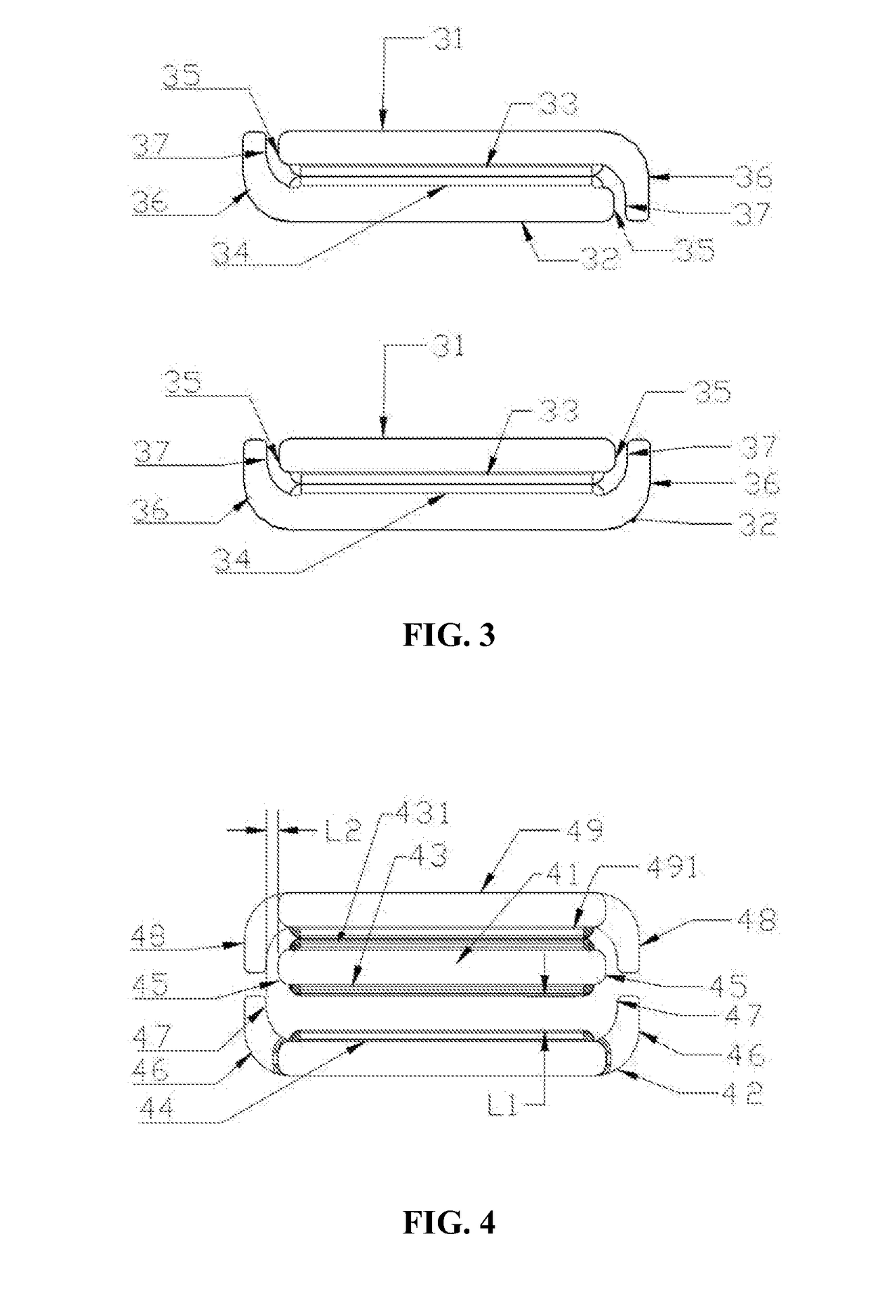
[0022]FIG. 3 shows a heavy current reed switch contact which is a normally closed structure. The reed switch contact comprises at least one pair of elastic reed electrodes (31, 32), or at least one fixed electrode (32, 31) and one elastic reed electrode (31, 32). The reed electrodes (31, 32) are made of conducting materials, and the surfaces of one end of the electrodes overlap. The opposite sides of the overlapped ends comprise contacts (33, 34). The end of the reed electrode (31, 32) in the vicinity of the contacts comprises a protruding arc discharge device (36). The end surfaces of the reed electrode (31, 32) overlap. The two electrode contacts (33, 34) are in a closed state.

[0023]The transformation process of the two electrodes (31, 32) between a closed state and an open state and the movement process of the electric arc between the contacts are similar to the open and closed processes in Example 1.


PUM


Abstract

A heavy current reed switch contact structure comprises at least one set of elastic reed electrode (11, 12) or at least one fixed electrode (12) and an elastic reed electrode (11). The reed electrode (11, 12) is made of a conductive material. Contacts (13, 14) are arranged on opposing surfaces of mutually overlapping ends. A side of the end having the contacts is disposed with an arc discharge device (16, 162). The reed switch employs a specially designed contact structure, and the arc discharge structure device is additionally disposed on the basis of a traditional switch contact structure. As a result, the reed switch quickly transfers to the contact arc discharge structure device an instantons arc generated upon switching the switch contact, thereby easing burnout resulting from an arc on the contact surfaces of the contacts, enabling the contacts to be less prone to being adhered together, and considerably increasing a bearing current and a switching capacity of the reed switch. The heavy current reed switch contact structure has a simple structure and provides a heavy bearing current.

Description

CROSS-REFERENCE TO RELATED APPLICATIONS[0001]This application is a National Stage Appl. filed under 35 USC 371 of International Patent Application No. PCT / CN2016 / 076060 with an international filing date of Mar. 10, 2016, designating the United States, now pending, and further claims foreign priority to Chinese Patent Application No. 201510132609.9 filed Mar. 25, 2015. Inquiries from the public to applicants or assignees concerning this document or the related applications should be directed to: Matthias Scholl P. C., Attn.: Dr. Matthias Scholl Esq., 245 First Street, 18th Floor, and Cambridge, Mass. 02142.BACKGROUND OF THE INVENTIONField of the Invention[0002]The invention relates to a switch contact which is a key component of electrical or electronic switches, and more particularly to a heavy current reed switch contact.Description of the Related Art[0003]Conventional reed switch contacts are produced according to a simple planar design. When the reed switch contacts are used in a...

Claims


Application Information

Patent Timeline
IPC IPC(8): H01H33/12H01H1/66H01H36/00
CPCH01H33/12H01H1/66H01H36/0006H01H1/26H01H9/46H01H1/06
Inventor JING, DEQIANG
Owner JING DEQIANG
Why Eureka
Try Eureka