Drip edge

a drip edge and drip edge technology, applied in the direction of roof drainage, roof covering, roofing, etc., can solve the problems of not working properly, the effectiveness of drip edges designed for flat roofs, and the pitch of roofs, so as to facilitate water coalescing, reduce scattering or splashing of roof runoff, and achieve effective installation

Active Publication Date: 2019-03-07
JAMES HARDIE TECH LTD
View PDF4 Cites 13 Cited by
  • Summary
  • Abstract
  • Description
  • Claims
  • Application Information

AI Technical Summary

Benefits of technology

[0005]The present disclosure provides various embodiments of a universal drip edge that can be effectively installed and used to protect fascia boards from roof water runoff regardless of the roof pitch. The present disclosure also provides various embodiments of a drip edge that can be reliably installed on roofs with sufficient room for a fascia board despite being installed before the fascia is attached. The present disclosure also provides various embodiments of a drip edge configured to facilitate water coalescing so that scattering or splashing of roof runoff is significantly reduced. In some embodiments, the drip edge has an inner footing and an outer section that may be independently angled relative to a tail of the drip edge. The drip edge has a double-layer tail that may provide a more robust product for installation and long-term performance following installation.

Problems solved by technology

Because the fascia boards are often installed after roofing is completed, drip edges are sometimes positioned too close to the eaves without leaving sufficient space for the fascia board to be installed behind the drip edge.
The effectiveness of a drip edge may also be affected by the pitch of the roof.
Drip edges designed for flat roofs do not function properly when installed on a high pitch roof and vice versa.

Method used


Image

  • Drip edge
  • Drip edge
  • Drip edge

Examples


Embodiment Construction

[0072]Although the present disclosure is described with reference to specific examples, it will be appreciated by those skilled in the art that the present disclosure may be embodied in many other forms. The embodiments discussed herein are merely illustrative and do not limit the scope of the present disclosure.

[0073]In the description which follows, like parts may be marked throughout the specification and drawings with the same or similar reference numerals. The drawing figures are not necessarily to scale and certain features may be shown exaggerated in scale or in somewhat generalized or schematic form in the interest of clarity and conciseness.

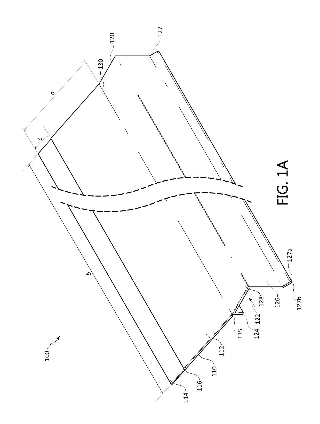
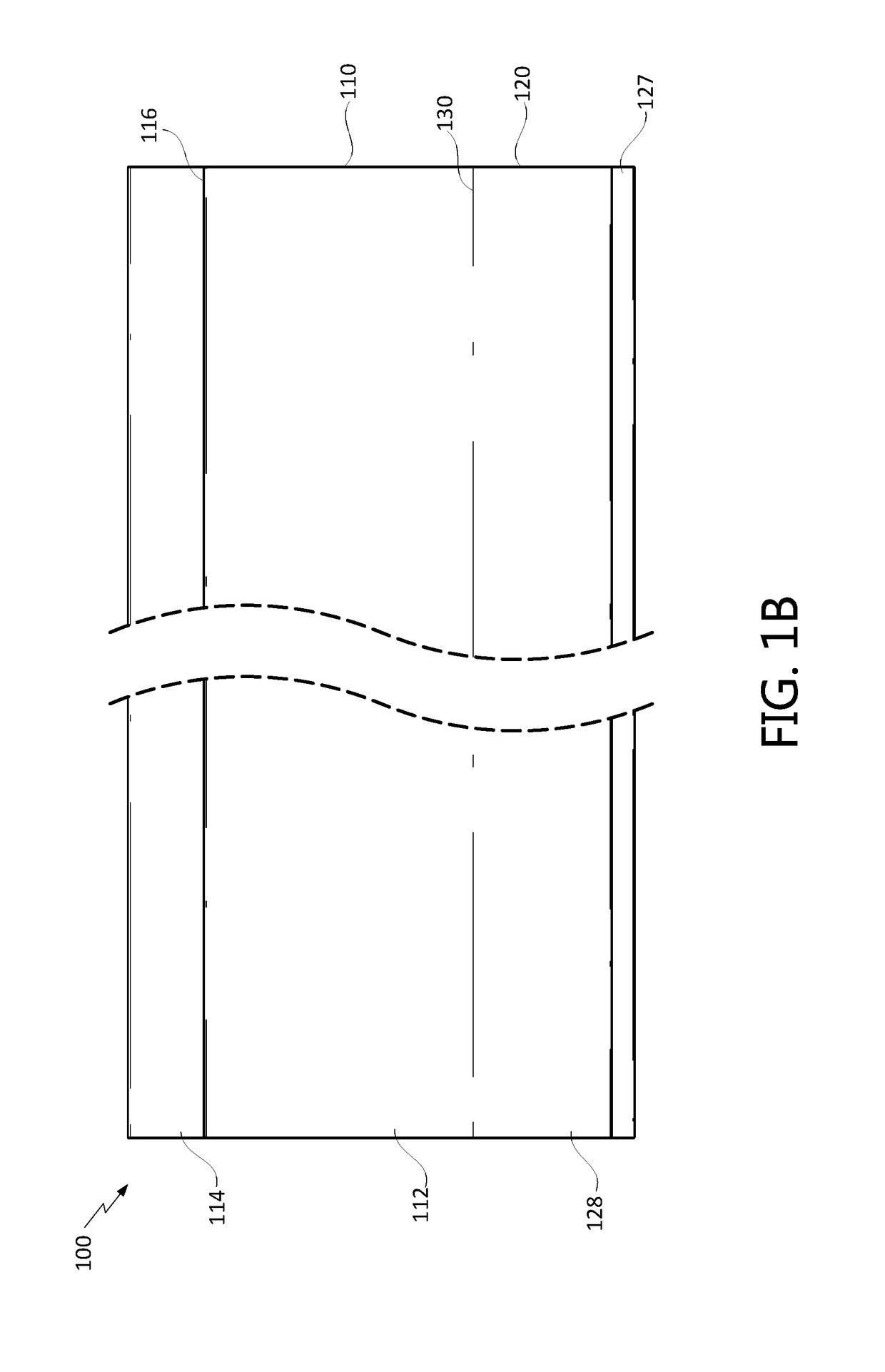
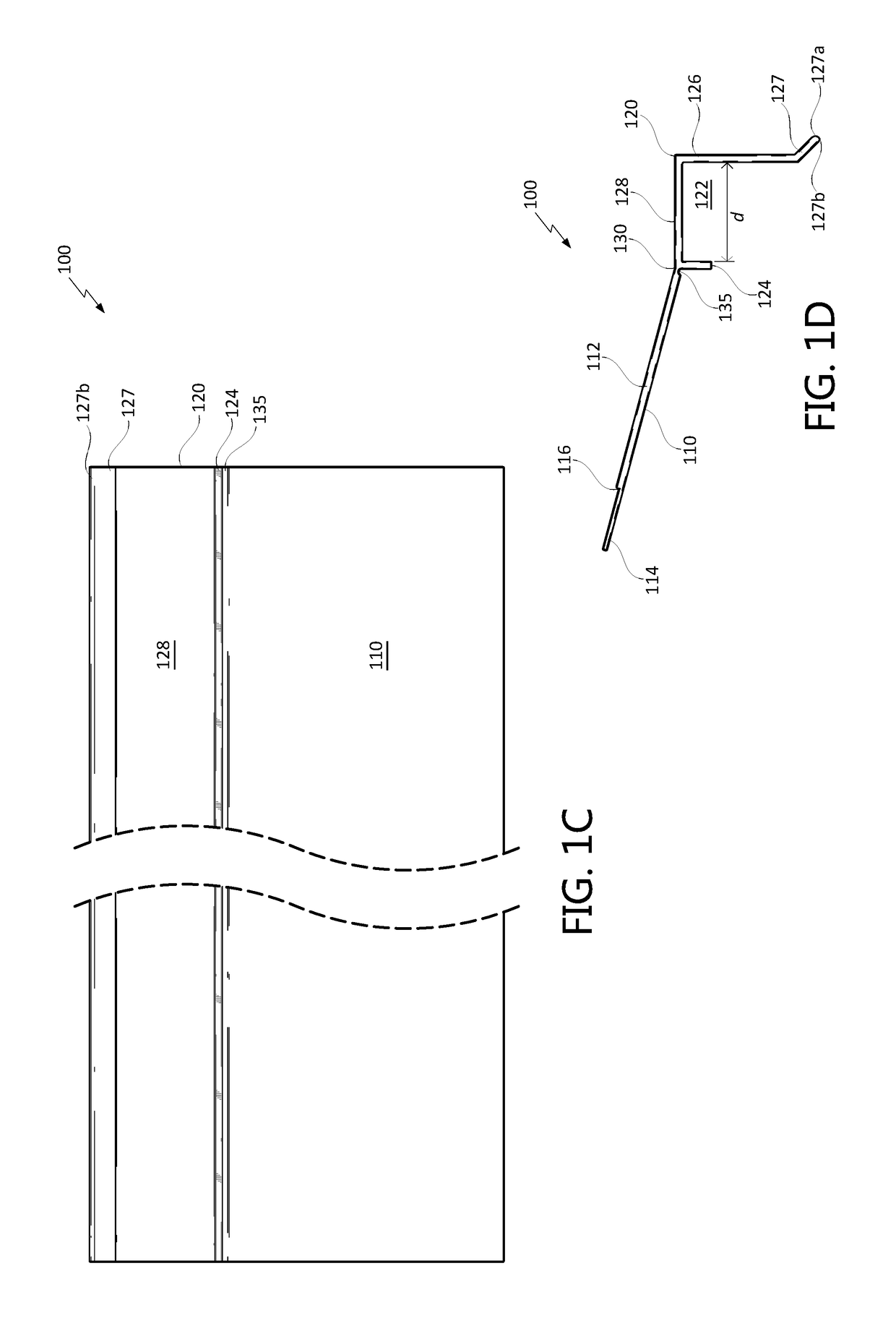
[0074]Generally described, this disclosure describes improved roof drip edges providing a variety of possible advantages over existing flashing systems. As will be described with reference to the figures, in some embodiments the drip edges described herein are advantageously configured to be installed by roofers so as to reliably provide...


PUM

PropertyMeasurementUnit
angleaaaaaaaaaa
angleaaaaaaaaaa
angleaaaaaaaaaa

Abstract

A customizable roof drip edge system includes an inner footing, an outer section, and a tail integrally formed with the inner footing and the outer section. The tail is nailable to a roof substrate. The outer section includes a bridging member connecting the tail to an outer footing. The bridging member and the outer footing are configured for directing the flow of water off of a roof. The inner footing is spaced from the outer footing by a suitable distance and configured to be placed against an eave as a positioning aid such that the drip edge can easily and reliably be installed with sufficient spacing for the installation of a fascia board after installation of the drip edge. The drip edge may be bendable to user-selectable angles between the tail and the inner footing and outer section to accommodate a range of roof pitches.

Description

CROSS-REFERENCE TO RELATED APPLICATIONS[0001]This application is a continuation-in-part of U.S. patent application Ser. No. 15 / 920,204, filed Mar. 13, 2018, entitled “DRIP EDGE,” which claims the benefit of U.S. Provisional Application Ser. No. 62 / 471,255, filed Mar. 14, 2017, entitled “DRIP EDGE,” both of which are hereby incorporated by reference in their entirety and for all purposes.BACKGROUNDField[0002]The present disclosure generally relates to weather resistant barrier systems, and more specifically to drip edge systems and methods.Description of the Related Art[0003]A drip edge can be installed at roof edges to guide water runoff away from fascia boards along roof linings and / or otherwise improve water management properties of the roof. The drip edge is typically a sheet of elongate metal bent across its length. The upper portion of the drip edge is inserted under the first course of roof shingles and attached to the roof while the lower portion extends downwardly from the e...

Claims


Application Information

Patent Timeline
Patent Type & Authority Applications(United States)
IPC IPC(8): E04D13/04B21D11/10
CPCE04D13/0459B21D11/10E04D2013/0468B21D5/16B21D19/00B21D47/00E04D13/15
Inventor DYE, THAYNEGEARHEART, JEREMY
Owner JAMES HARDIE TECH LTD
Why Eureka
Try Eureka