Coil component
- Summary
- Abstract
- Description
- Claims
- Application Information
AI Technical Summary
Benefits of technology
Problems solved by technology
Method used
Image

Examples
first embodiment
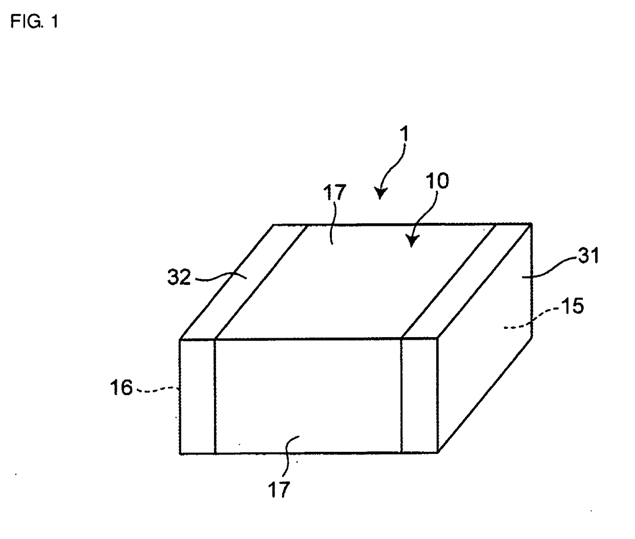
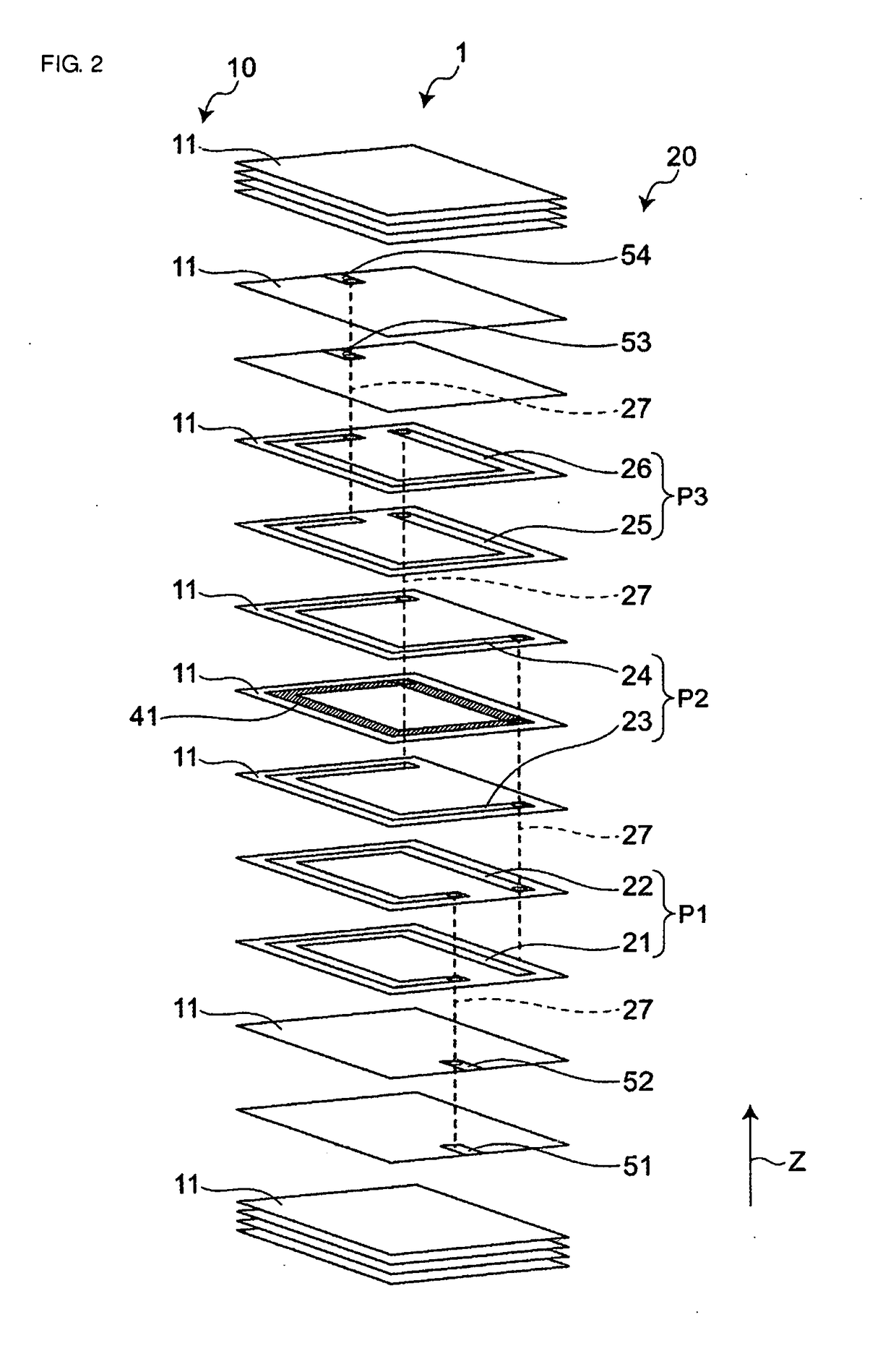
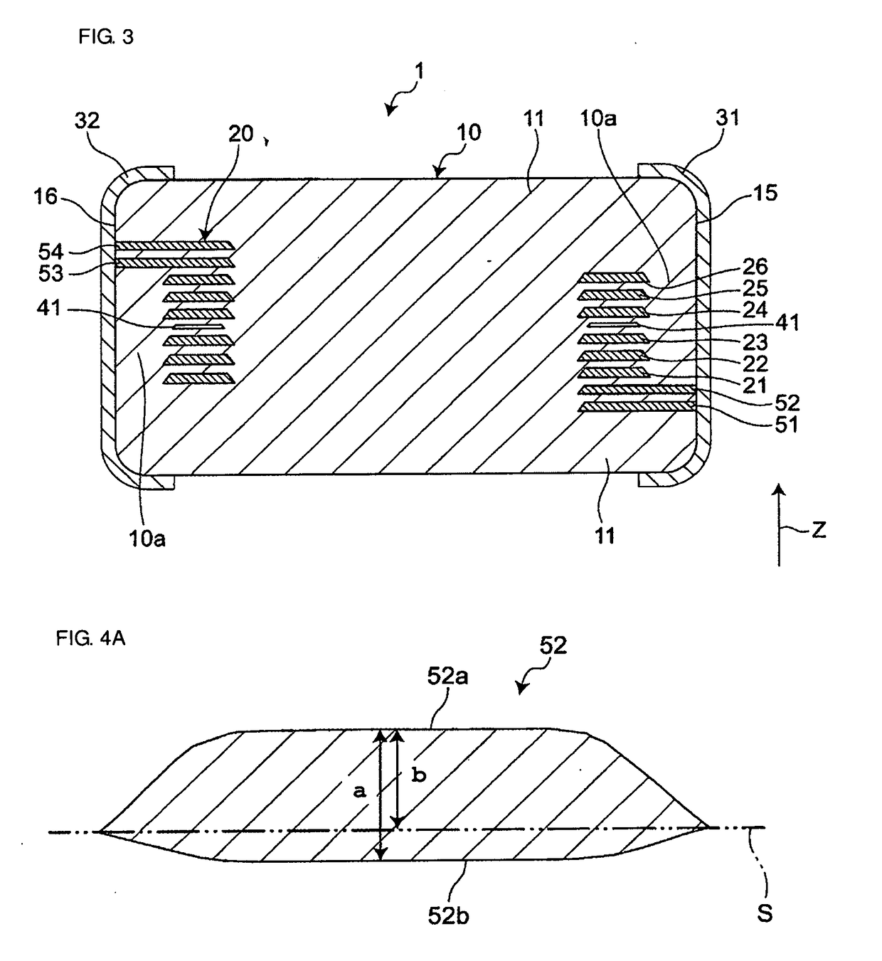
[0039]FIG. 1 is a perspective view of a coil component according to a first embodiment of the present disclosure. FIG. 2 is an exploded perspective view of the coil component. FIG. 3 is a sectional view of the coil component. As illustrated in FIGS. 1, 2 and 3, the coil component 1 includes a base body 10, a coil 20 disposed inside the base body 10, a first outer electrode 31, and a second outer electrode 32, the first and second outer electrodes 31 and 32 being disposed on surfaces of the base body 10 and electrically connected to the coil 20.
[0040]The coil component 1 is electrically connected to wirings on or in a circuit board (not illustrated) via the first and second outer electrodes 31 and 32. The coil component 1 is used as an electromagnetic interference suppression filter, for example, and is utilized in a variety of electronic devices such as a personal computer, a DVD player, a digital camera, a TV, a cellular phone, and car electronics.
[0041]The base body 10 includes a ...
second embodiment
[0076]FIG. 6 is an exploded perspective view of a coil component according to a second embodiment of the present disclosure. FIG. 7 is a sectional view taken along a lateral surface of the coil component. FIG. 8 is a sectional view taken along a first end surface of the coil component. The second embodiment is different from the first embodiment in configuration of the cavity. The different configuration between both the embodiments will be described below. Other constituent elements are the same as those in the first embodiment, and description of those constituent elements is omitted while those constituent elements are denoted by the same reference signs as in the first embodiment.
[0077]As illustrated in FIGS. 6, 7 and 8, the coil component 1A according to the second embodiment includes one first cavity 41 overlapping the first and second lead-out conductor portions 51 and 52 in the first direction Z, and one second cavity 42 not overlapping the first and second lead-out conducto...
third embodiment
[0087]FIG. 9 is a sectional view of a coil component according to a third embodiment of the present disclosure. The third embodiment is different from the second embodiment in configuration of the coil conductor portions and the cavity. The different configuration between both the embodiments will be described below. Other constituent elements are the same as those in the second embodiment, and description of those constituent elements is omitted while those constituent elements are denoted by the same reference signs as in the second embodiment.
[0088]As illustrated in FIG. 9, in the coil component 1B according to the third embodiment, each of the coil conductor portions 21 to 26 includes a plurality (two in this embodiment) of coil conductor layers 200 that are laminated in the first direction Z in a surface contact state therebetween. In other words, the coil conductor portions 21 to 26 are each formed by coating the coil conductor layer 200 plural times. Accordingly, a cross-sect...
PUM
 Abstract
Description
Claims
Application Information
 - Generate Ideas
- Intellectual Property
- Life Sciences
- Materials
- Tech Scout
- Unparalleled Data Quality
- Higher Quality Content
- 60% Fewer Hallucinations
Browse by: Latest US Patents, China's latest patents, Technical Efficacy Thesaurus, Application Domain, Technology Topic, Popular Technical Reports.
© 2025 PatSnap. All rights reserved.Legal|Privacy policy|Modern Slavery Act Transparency Statement|Sitemap|About US| Contact US: help@patsnap.com