
Cleaning apparatus and pv module cleaning system

a cleaning apparatus and cleaning technology, applied in the field of photovoltaic power station cleaning apparatus, can solve the problems of affecting the absorption of light to a great extent, photovoltaic power station, most of them using manual cleaning, etc., to save labor costs, improve work efficiency, and increase power generation

Inactive Publication Date: 2019-03-07
HANGZHOU PINNET TECH CO LTD
View PDF1 Cites 6 Cited by
  • Summary
  • Abstract
  • Description
  • Claims
  • Application Information

AI Technical Summary

Benefits of technology

The cleaning apparatus described in this patent is a simple and cost-effective device used for cleaning photovoltaic panels. It includes a sweeper, a mobile terminal, a guiding rail, and a control system. The device is designed to be easily moved and controlled, and it uses the mobile terminal to stop and clean the panels on the guiding rail. By repeating this cleaning process over time, the device can efficiently and automatically clean photovoltaic power stations, saving labor costs, improving work efficiency, and increasing power generation. Overall, this invention provides economic and ecological benefits for photovoltaic power generation.

Problems solved by technology

The sand, dust and industrial pollutants in the natural cover the surface of the solar panel, which affects the absorption of the light to a great extent.
Generally, the area of the photovoltaic power station is large, and currently most of them use manual cleaning with low efficiency, long cycle, and high cost.

Method used


Image

  • Cleaning apparatus and pv module cleaning system
  • Cleaning apparatus and pv module cleaning system
  • Cleaning apparatus and pv module cleaning system

Examples


embodiment 1

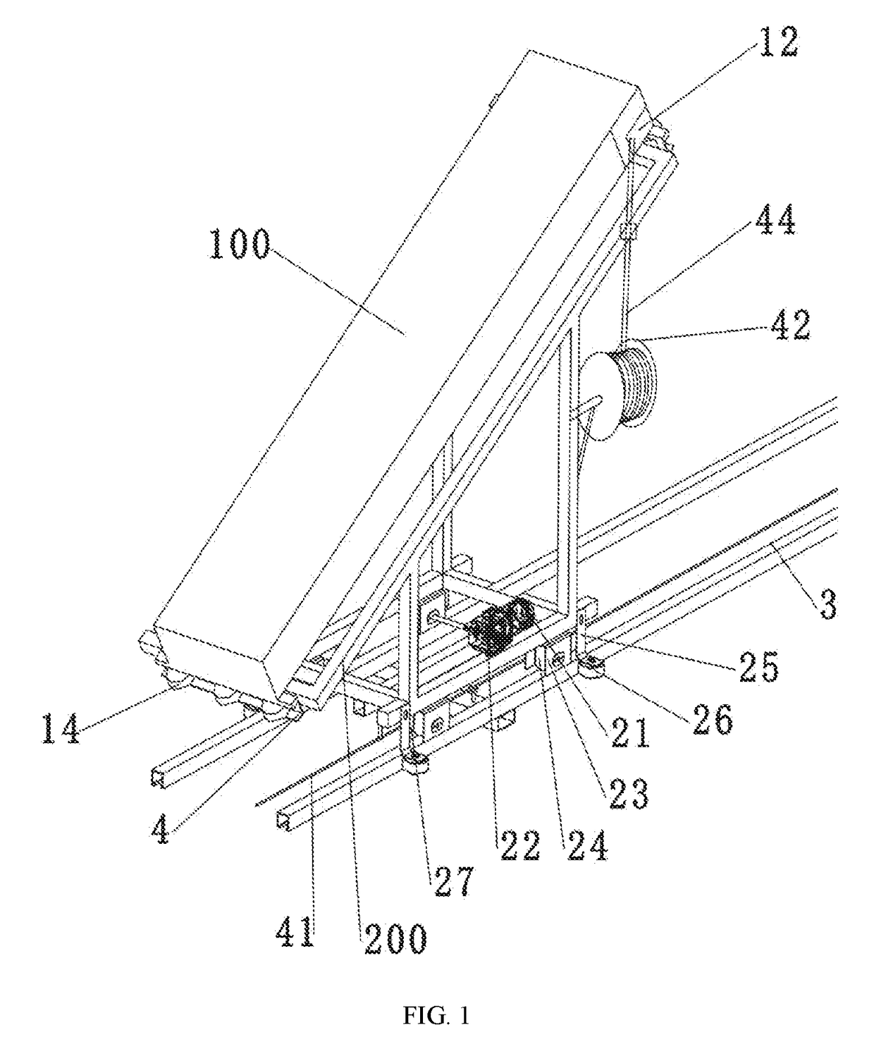
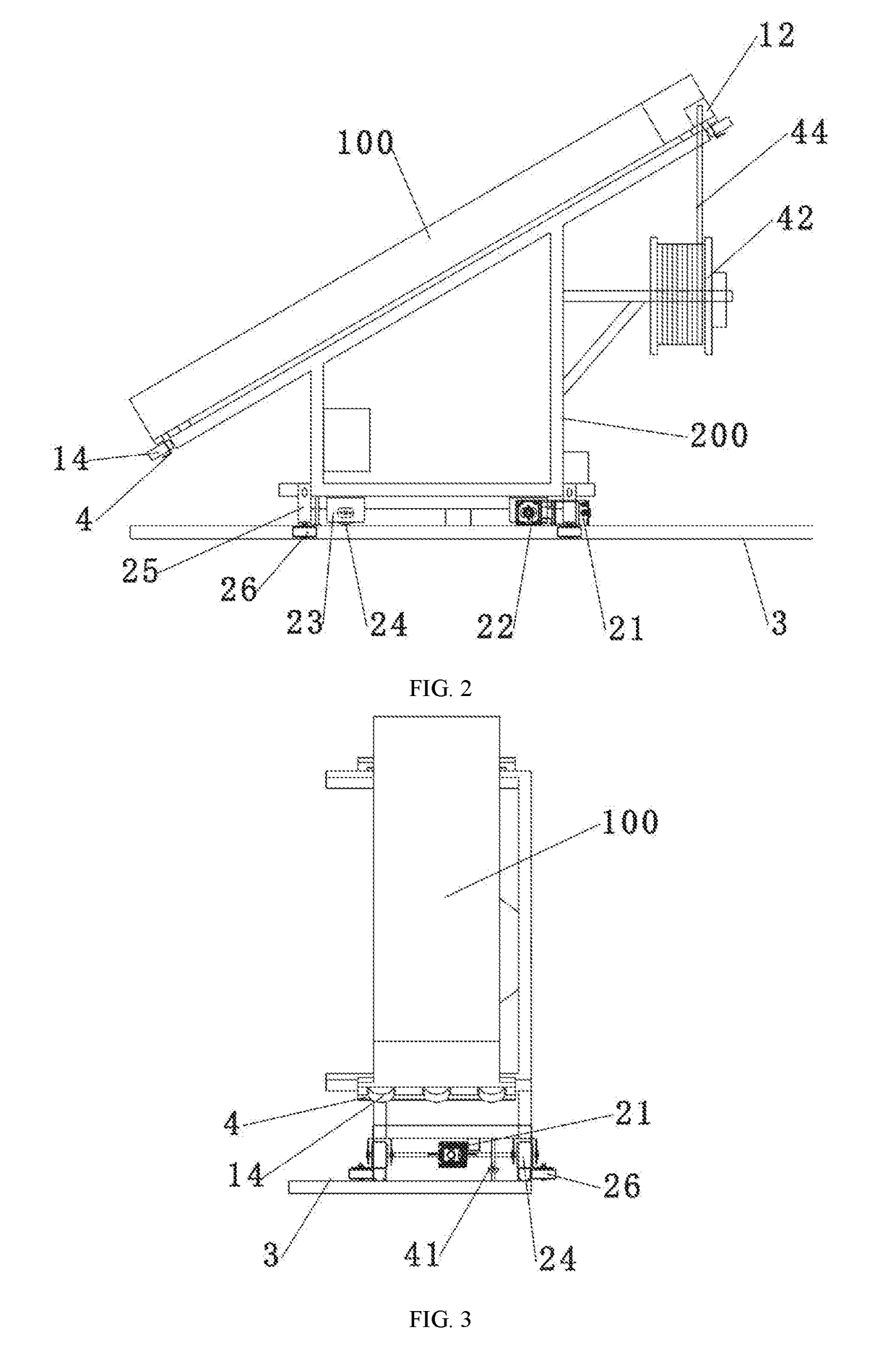
[0027]The technical solution adopted by the present invention is cleaning apparatus, including: a sweeper 1, a mobile terminal 2, a guiding rail 3, and a control system. The mobile terminal 2 is used for bearing the sweeper 1 and walks along the guiding rail 3 under the control of the control system, and the sweeper 1 can move on the mobile terminal 2 under the control of the control system.

[0028]The mobile terminal 2 includes a loading frame 200, a first drive device, and a first walking mechanism. The sweeper 1 is placed on the loading frame 200 firmly. The loading frame 200 has a certain inclination angle, and the inclination angle is consistent with photovoltaic (PV) array panels 500. The sweeper 1 can be clamped on the loading frame 200 by a clamping block 4. The first drive device includes a transmission-connected first motor 21 and a reduction gearbox 22. During working, the first motor 21 drives the reduction gearbox 22 after being powered on, and the reduction gearbox 22 th...

embodiment 2

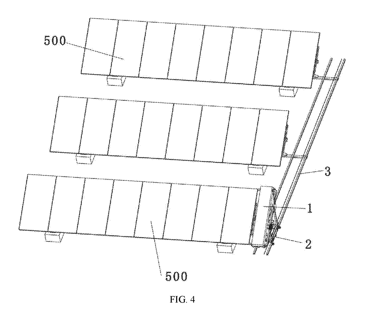
[0032]A PV module cleaning system using the cleaning apparatus in embodiment 1, the PV array panels are a m*n matrix, and both m and n are positive integers. FIG. 4 describes a matrix of m=1 and n=3. During working, the guiding rail 3 is disposed at one side of the PV array panels 500, the mobile terminal 2 is disposed above the guiding rail 3, and the sweeper 1 is loaded on the bearing frame 200 of the mobile terminal 2. The inclination angle of the bearing frame 200 is substantially consistent with the inclination angle of the PV array panels 500, so as to be cleaner for cleaning and not to hinder the operation of the sweeper. The inclination angle allows a certain tolerance, when the angular tolerance exists, the height of the sweeper 1 should be adjusted properly by adjusting the height of the bearing frame 200 properly to ensure the operation is not hindered. The sweeper 1 is on the upper surface of the PV array panels 500, and the cleaning head 10 is just close to the “fugitiv...


PUM


Abstract

The present invention discloses cleaning apparatus and a PV module cleaning system. The cleaning apparatus includes a sweeper, a mobile terminal, a guiding rail and a control system. The mobile terminal is used for bearing the sweeper and walks along the guiding rail under the control of the control system, and the sweeper can move on the mobile terminal under the control of the control system; and the PV module cleaning system includes PV array panels, the PV array panels are m*n matrix, both m and n are positive integers, the guiding rail is located at one side of the PV array panels, the mobile terminal is located above the guiding rail, the sweeper is loaded on the bearing frame of the mobile terminal, and the sweeper reciprocates on the PV array panels through a walking mechanism.

Description

BACKGROUND OF THE INVENTIONField of the Invention[0001]The present invention relates to a photovoltaic (PV) power station cleaning apparatus and, more particularly, to a cleaning apparatus and a PV module cleaning system.Description of the Related Art[0002]The main power generation apparatus of a solar photovoltaic (PV) power station is a solar photovoltaic panel, and the power generation of the solar photovoltaic panel depends on the intensity of incident sunlight. However, the PV array panels are installed in the open air. The sand, dust and industrial pollutants in the natural cover the surface of the solar panel, which affects the absorption of the light to a great extent. According to statistics, the loss can account for 5%-8% of the total solar power generation, or even more. Therefore, it is necessary to often carry out a dust cleaning for the surface of the solar panel at an appropriate time to reduce dust accumulation and improve the benefit of the power station. Generally,...

Claims


Application Information

Patent Timeline
IPC IPC(8): H02S40/10B08B1/00B08B11/04
CPCH02S40/10B08B1/001B08B11/04B08B13/00F24S40/20Y02E10/40Y02E10/50B08B1/30B08B1/143B08B1/12B08B1/10
Inventor CHEN, WENYONGZHAO, SIBOWANG, LONGLIANG, ZHONGTANGJIANG, BANGYOUMA, LINZHU, WENPING
Owner HANGZHOU PINNET TECH CO LTD
Learn More