Virtual image display device

a virtual image and display device technology, applied in the direction of polarising elements, magnifying glasses, instruments, etc., can solve the problems of image quality affected, difficult to position a lens that fits a human face, etc., to suppress aberration derived, reduce the weight of the lens, and suppress the generation of birefringence

Inactive Publication Date: 2019-03-14
SEIKO EPSON CORP
View PDF8 Cites 1 Cited by
  • Summary
  • Abstract
  • Description
  • Claims
  • Application Information

AI Technical Summary

Benefits of technology

[0014]In still another aspect of the disclosure, the asymmetric lens may be a resin lens with a property of zero birefringence or low birefringence. As the resin lens with a property of zero birefringence or low birefringence, a resin lens whose orientational birefringence is not greater than 0.01 and not less than −0.01, or whose photoelastic constant is not greater than 10 [10−12 / Pa] can be considered. In this case, suppressing the generation of birefringence makes it possible to suppress aberration derived from a material and the like, and reduce the weight of the lenses leading to the reduction in weight of the whole device while maintaining optical performance to enhance image quality.
[0015]In still another aspect of the disclosure, an attachment section for attaching constituent elements may be further included, and the attachment section may include a position determining portion, the position determining portion being configured to make contact with the lens end face and position the lens end face when the asymmetric lens is to be attached. In this case, by the lens end face making contact with the position determining portion of the attachment section, the attachment of the asymmetric lens can be carried out with high precision and high efficiency.
[0016]In still another aspect of the disclosure, a distance from a position at which the eye of an observer is assumed to be present to a position of the asymmetric lens may be within a range from 10 to 30 mm. In this case, the observer can wear the above-described device as an eyeglass-type device without an uncomfortable feeling.
[0017]In still another aspect of the disclosure, an optical component disposed before the asymmetric lens may be further included, and the optical component may include an end face formed in a shape corresponding to the lens end face of the asymmetric lens. In this case, along with the asymmetric lens, the optical component disposed on the asymmetric lens can be reduced in size and weight, for example, or the position of the optical component can be precisely and efficiently determined.
[0018]In still another aspect of the disclosure, as optical components, there may be provided a display-side lens which is disposed before the asymmetric lens, the display-side lens being configured to allow the image light from the image element to be incident on, a half mirror disposed before the display-side lens, and a semi-transmissive polarization plate disposed between the asymmetric lens and the display-side lens, the semi-transmissive polarization plate being configured to transmit a component in a polarization transmission axis direction. In this case, disposing the half mirror in a light path makes it possible to bend the light path to achieve a wide angle of view and a reduction in size.
[0019]In still another aspect of the disclosure, the image element may include an end face formed in a shape corresponding to the lens end face of the asymmetric lens. In this case, it is possible to achieve reductions in size and weight of the image element and consequently the reductions in size and weight of the device while considering the fitting of the device to the human face.

Problems solved by technology

In addition, with an increase in lens size or the like, such issues may arise that the disposition of a lens that fits a human face becomes difficult, image quality is affected, and the like.

Method used


Image

  • Virtual image display device
  • Virtual image display device
  • Virtual image display device

Examples


first exemplary embodiment

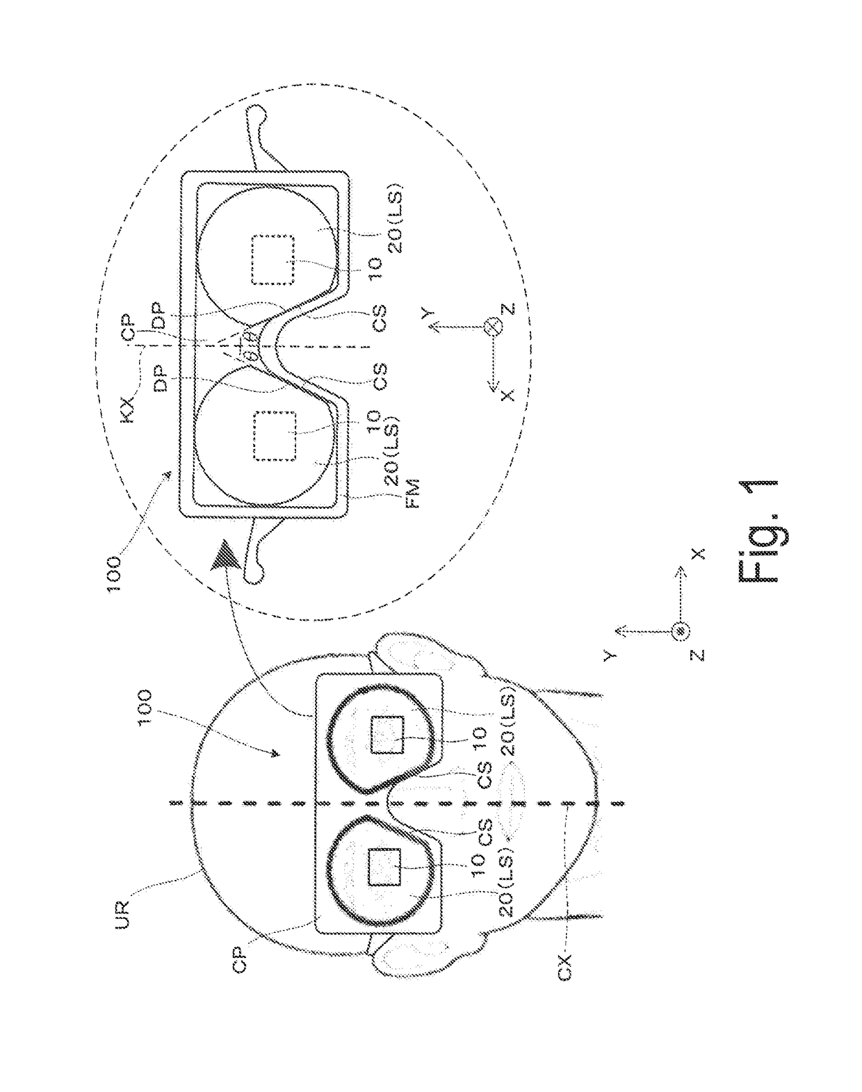
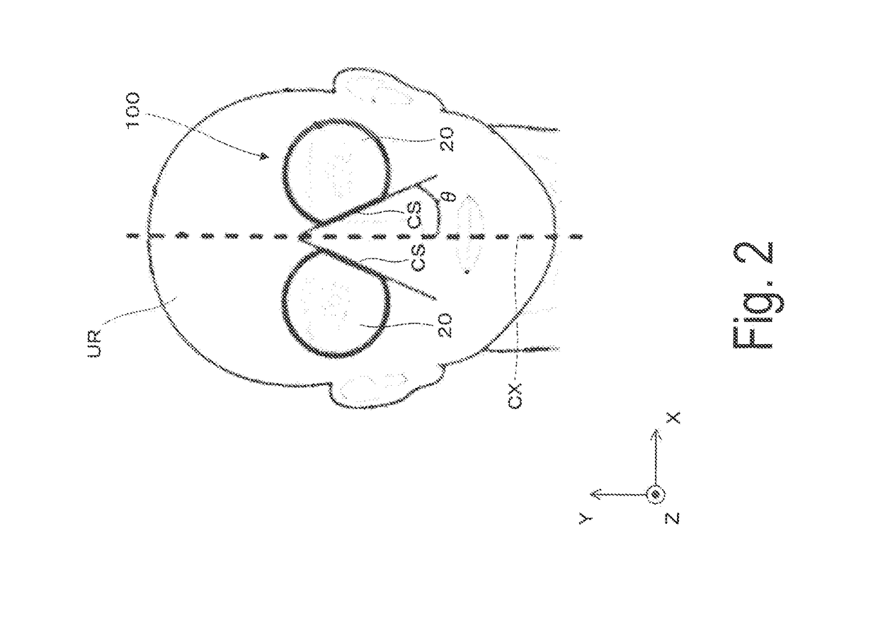
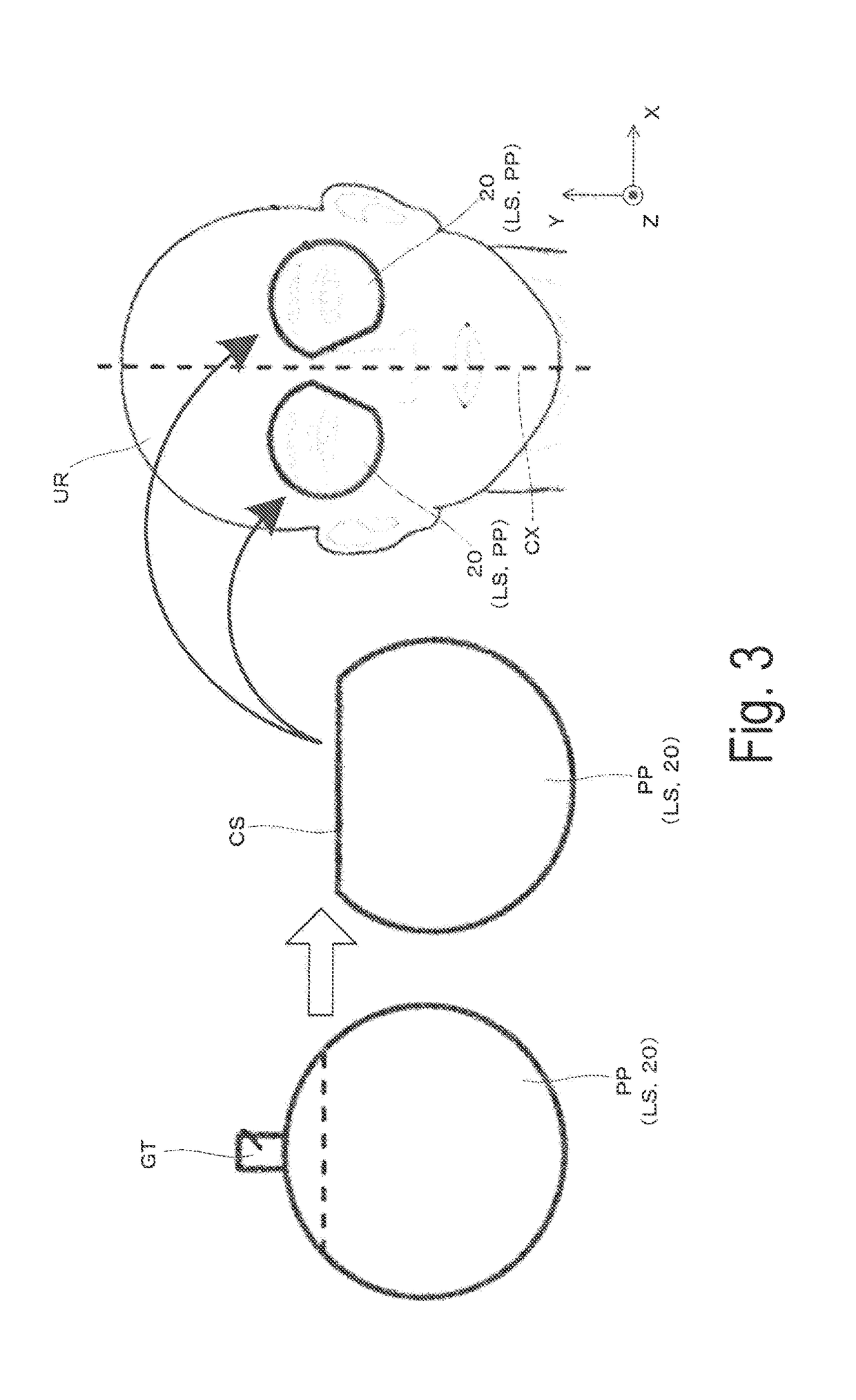
[0038]Hereinafter, a virtual image display device according to First Exemplary Embodiment of the disclosure will be described in detail with reference to FIG. 1 and the like.

[0039]As conceptually illustrated in FIG. 1 and FIG. 4, a virtual image display device 100 of the exemplary embodiment includes an image display unit 10 as an image element (image display section) and an enlargement optical system 20, and serves as a virtual image display device, that is, a head mount display (HMD) capable of causing an observer or a user wearing the virtual image display device 100 to visually recognize picture light (image light) by a virtual image. As illustrated in FIG. 1, the image display unit 10, the enlargement optical system 20, and the like are accommodated and protected in an outer packaging unit CP. Here, as illustrated in FIG. 4 and the like, in the virtual image display device 100 according to the exemplary embodiment, an optical axis AX of the optical system extends in a Z directi...

second exemplary embodiment

[0066]Hereinafter, a virtual image display device according to Second Exemplary Embodiment will be described with reference to FIG. 10. In a virtual image display device according to the exemplary embodiment, lenses serving as the main member in an enlargement optical system is configured of a plurality of lenses, while in the virtual image display device of First Exemplary Embodiment, the lens serving as the main member in the enlargement optical system is configured of a single cut lens. As such, the virtual image display device of the exemplary embodiment differs from First Exemplary Embodiment in that point. An exterior appearance configuration and the attachment of the enlargement optical system are similar to those of First Exemplary Embodiment (see FIG. 1), and thus illustrations and descriptions of the exterior appearance configuration and of the attachment of the enlargement optical system are omitted.

[0067]A virtual image display device 200 according to the exemplary embod...


PUM


Abstract

By removing part of a lens effective diameter range in a cut lens, a lens is reduced in size and weight in an HMD that trends toward a larger device size. At this time, by making an area to be removed within the lens effective diameter range to be an area on a nose side, reductions in size and weight can be achieved while considering influence on image quality or fitting to a human face.

Description

[0001]The present application is based on and claims priority from JP Application Serial Number 2017-176454, filed Sep. 14, 2017, the disclosure of which is hereby incorporated by reference herein in its entirety.BACKGROUND1. Technical Field[0002]The disclosure relates to a virtual image display device that is mounted on the head and provides an image formed by an image element or the like to an observer.2. Related Art[0003]In recent years, a virtual image display device (or a head mounted-type display device) such as a head mount display (hereinafter, also referred to as “HMD”) to be mounted on the head of an observer has come to support a wide angle of view. In order to support a wide angle of view, lenses are, in general, likely to become large in diameter, thickness, and the like. However, in the case of the HMD, the lenses are also requested to be small in size and light in weight. In addition, with an increase in lens size or the like, such issues may arise that the dispositio...

Claims


Application Information

Patent Timeline
Patent Type & Authority Applications(United States)
IPC IPC(8): G02B27/01G02B27/09G02B5/30
CPCG02B27/0172G02B27/0977G02B27/0955G02B5/3083G02B2027/0178G02B17/0856G02B17/086G02B25/001G02B27/286
Inventor MIYAO, TOSHIAKITAKAGI, MASAYUKITAKEDA, TAKASHIKOMATSU, AKIRAYAMAGUCHI, TOKITO
Owner SEIKO EPSON CORP
Why Eureka
Try Eureka