
Clinical laboratory test apparatus and system

Active Publication Date: 2019-03-14
FUJIFILM CORP
View PDF6 Cites 0 Cited by
  • Summary
  • Abstract
  • Description
  • Claims
  • Application Information

AI Technical Summary

Benefits of technology

The invention is designed to improve the accuracy and efficiency of optically readable code array, such as barcodes, in clinical laboratory tests. The apparatus can determine the authenticity of the code array using only the test apparatus and can smoothly manage the system that includes the test apparatus. This technology helps streamline the testing process and ensures accuracy in the laboratory tests.

Problems solved by technology

In a case where dirt, dust, or the like is attached to the barcode of the sample container, there is a concern that the barcode is read erroneously by the clinical laboratory test apparatus.
Further, since barcodes are given to various products, there is also a concern that a barcode that is not related to the barcode used in the clinical laboratory test is read by the clinical laboratory test apparatus.
The erroneously read test information does not match any test order managed by the server, and thus, it is necessary to perform matching, through a manual operation, between the test result and the test order that are associated with the erroneously read test information, which imposes a burden on a manager of the system.
Further, a medical care for a test subject is delayed until the matching is completed.
In addition, in a case where even the matching through the manual operation is unavailable, re-test is necessary, which also imposes a burden on the test subject.
However, a configuration in which the list of the test orders is transmitted to the clinical laboratory test apparatus from the server needs bi-directional communication between the clinical laboratory test apparatus and the server, which may lead to complication of the system.
Further, in a case where the clinical laboratory test apparatus cannot acquire the list of the test orders due to communication interference or the like, it causes a hindrance in execution of the test.

Method used


Image

  • Clinical laboratory test apparatus and system
  • Clinical laboratory test apparatus and system
  • Clinical laboratory test apparatus and system

Examples


Embodiment Construction

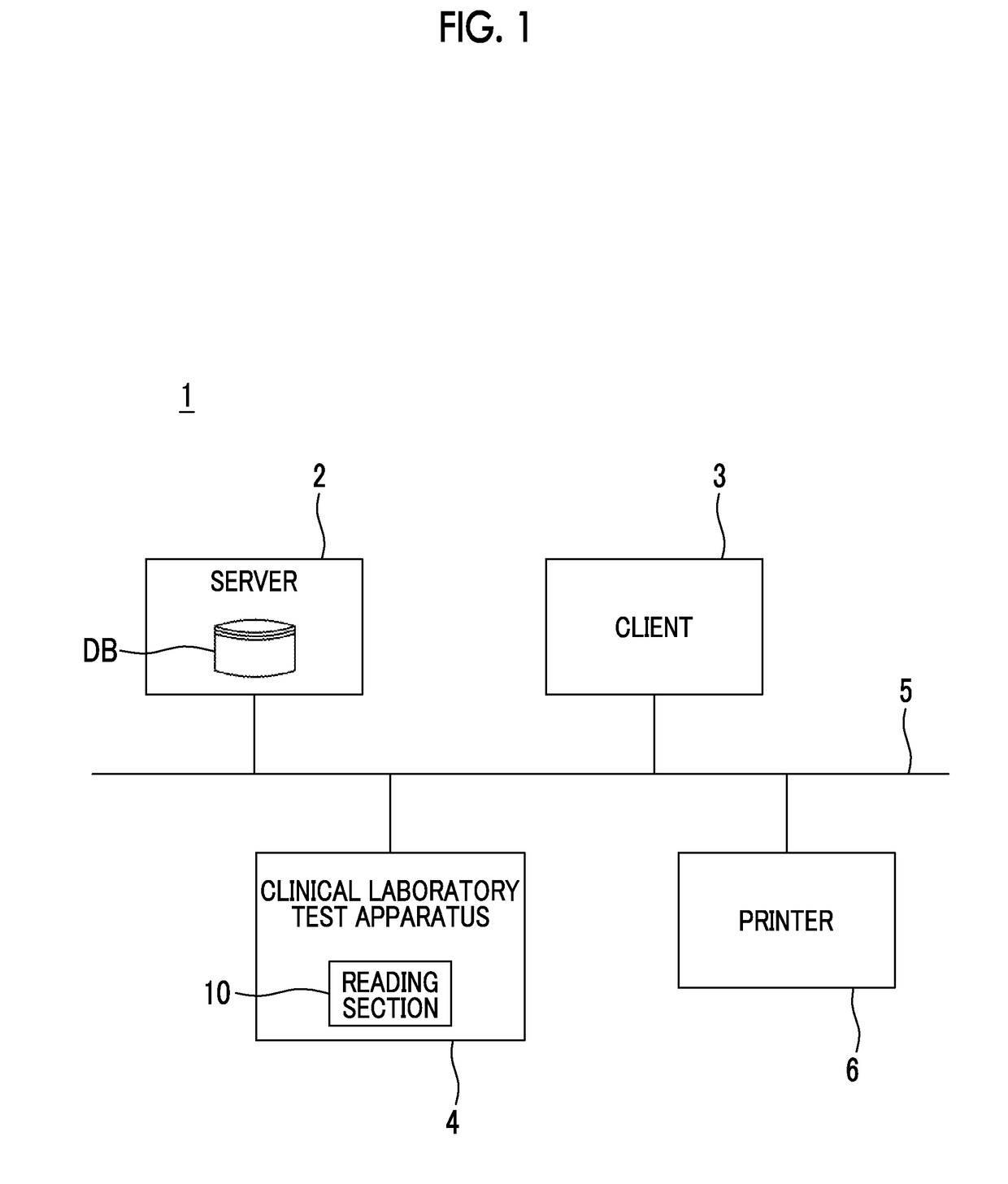
[0042]FIG. 1 shows an example of a medical information system, for illustrating an embodiment of the invention.

[0043]A medical information system (hereinafter, simply referred to as a system) 1 is a system that is introduced to a health care organization such as a hospital and manages a test order and a test result of a clinical laboratory test performed in the health care organization. The clinical laboratory test means a test for analyzing components with respect to a sample such as blood, viscous liquid, or urine gathered from a test subject (for example, a patient) for detecting viruses or bacteria.

[0044]The system 1 includes a server 2, a client 3, and a clinical laboratory test apparatus 4. Here, the server 2, the client 3, and the clinical laboratory test apparatus 4 are connected to each other through a network 5 such as a local area network (LAN).

[0045]The server 2 is a computer that includes a processor such as a central processing unit (CPU), a memory such as a read only ...


PUM


Abstract

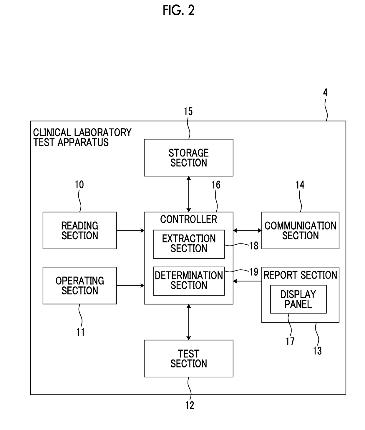
A clinical laboratory test apparatus of a health care information system includes a reading section that reads an optically readable code array, an extraction section that extracts, from a plurality of the code arrays read by the reading section, a rule that is common between the plurality of code arrays, a storage section that stores the rule extracted by the extraction section, and a determination section that determines authenticity of each of the code arrays read by the reading section based on the rule stored in the storage section. In testing a sample, in a case where it is determined by the determination section that the code array read by the reading section is true, the test is executed, and in a case where it is determined that the code array is false, the execution of the test is suspended.

Description

CROSS-REFERENCE TO RELATED APPLICATIONS[0001]This application claims the benefit of Japanese Patent Application JP 2017-174907, filed Sep. 12, 2017, the entire content of which is hereby incorporated by reference, the same as if set forth at length.BACKGROUND OF THE INVENTION1. Field of the Invention[0002]The present invention relates to a clinical laboratory test apparatus and system.2. Description of the Related Art[0003]A health care organization such as a hospital uses a medical information system that manages a test order and a test result for a clinical laboratory test performed in the health care organization. A barcode is given to a sample container that contains a sample (for example, blood, viscous liquid, or the like) gathered for the clinical laboratory test, and test information (for example, a test subject identification (ID), a test date, a test type, or the like) for specifying the test order is retained in the barcode.[0004]In the clinical laboratory test apparatus,...

Claims


Application Information

Patent Timeline
IPC IPC(8): G16H10/40G06K7/10B01L3/00G01N35/00
CPCG16H10/40G06K7/10861B01L3/5453G01N35/00732B01L2300/021G01N2035/00752G06K19/06028
Inventor ODA, YOSHINARI
Owner FUJIFILM CORP
Learn More