Seismic grooveless coupling

a grooveless, coupling technology, applied in the direction of fluid pressure sealing joints, sleeve/socket joints, fastening means, etc., can solve the problems of fluid leakage, vibration generation, poor fluid flow of coupling, etc., to achieve easy bursting and easy insertion

Inactive Publication Date: 2019-03-21
NAM SANG KEON
View PDF0 Cites 11 Cited by
  • Summary
  • Abstract
  • Description
  • Claims
  • Application Information

AI Technical Summary

Benefits of technology

[0029]According to the seismic grooveless coupling according to embodiments of the present invention, incised groove mounting protrusion parts, which are reinforcing members formed on both sides of a packing, are mounted in incised grooves formed in upper and lower coupling segments, and thus a side of the packing can be prevented from easily bursting by a pressure.
[0030]According to the seismic grooveless coupling according to embodiments of the present invention, spacing elastic members, which are a rubber tube with a predetermined length, are disposed between both ends of the upper and lower coupling segments fastened by a fastening unit, and thus the pipes can be easily inserted.
[0031]According to the seismic grooveless coupling according to embodiments of the present invention, a plurality of sawtooth-shaped sealing lips are provided in pipe sealing units on both ends of a packing attached to an outer circumferential surface of the pipe, and thus sealing can be easily performed even though an end of the pipes escapes from any one or two of the sealing lips when the pipes expand or contract.

Problems solved by technology

However, forming the circle-shaped outer groove on the pipe has many problems in which preparation of a work space and a process of forming the circle-shaped outer groove after installation of a machine are complicated and difficult, a flow of fluid is not good, and vibration is generated because a predetermined amount of the circle-shaped outer groove protrudes from an inner diameter when the circle-shaped outer groove is formed such that the flow of fluid is interrupted.
Also, the coupling has a fluid leakage when the pipe expands and contracts.
Due to parts protruding from inner sides of the coupling segments and inserted into the circle-shaped outer grooves of the pipes, the bolt and the nut are not easily tightened, and thus there are problems in which an assembly work is very difficult and a lot of work time are required.

Method used


Image

  • Seismic grooveless coupling
  • Seismic grooveless coupling
  • Seismic grooveless coupling

Examples


first embodiment

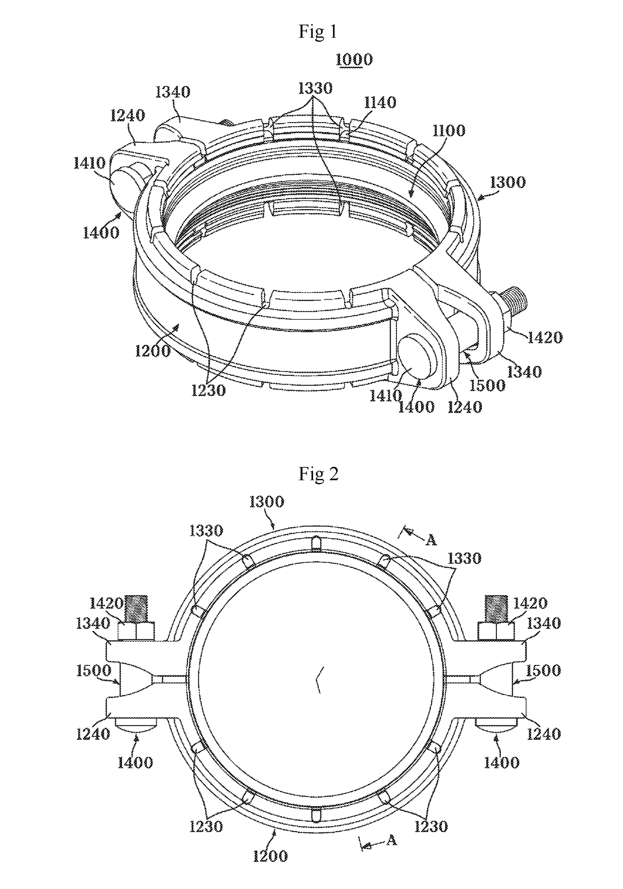
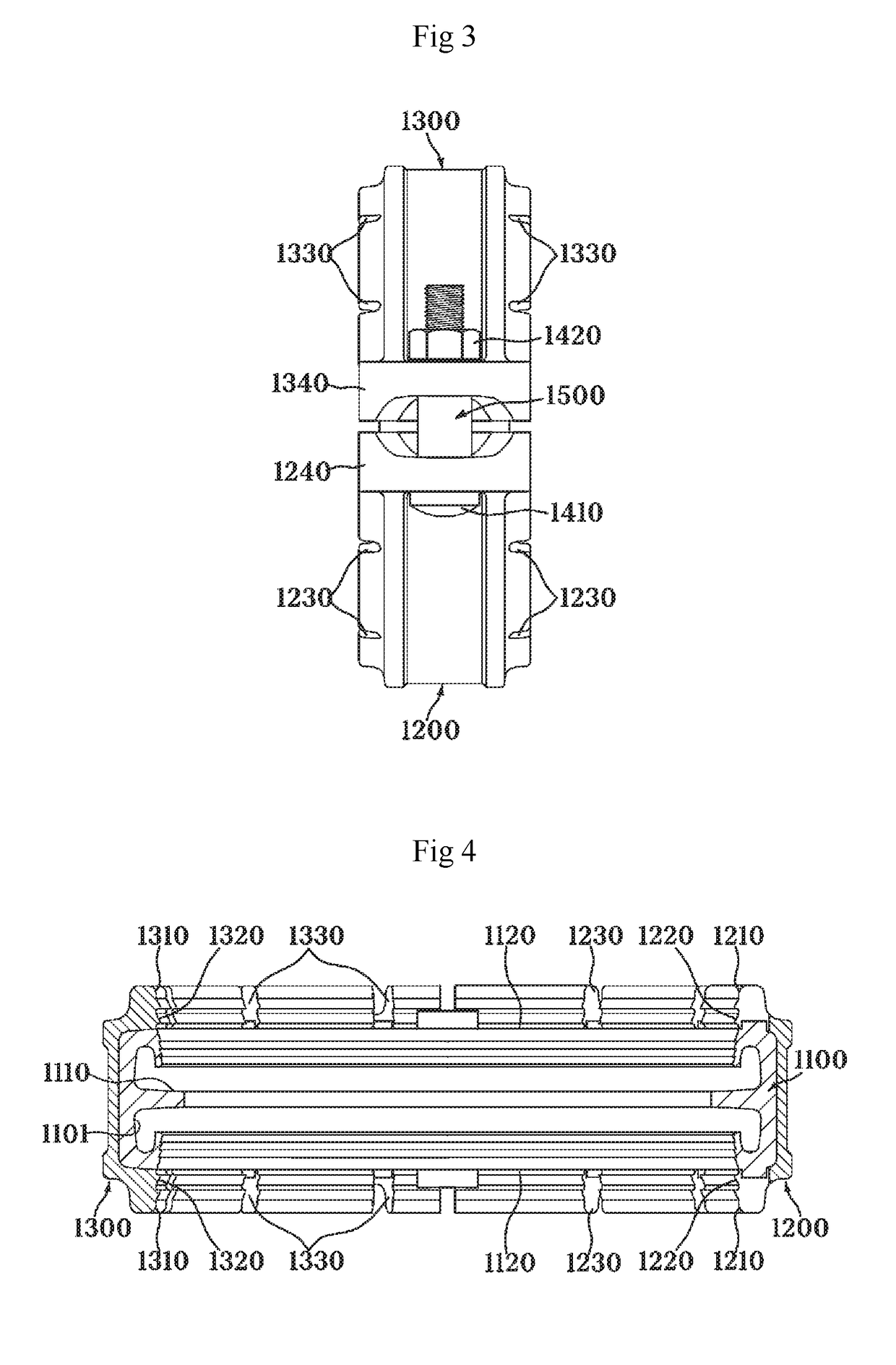
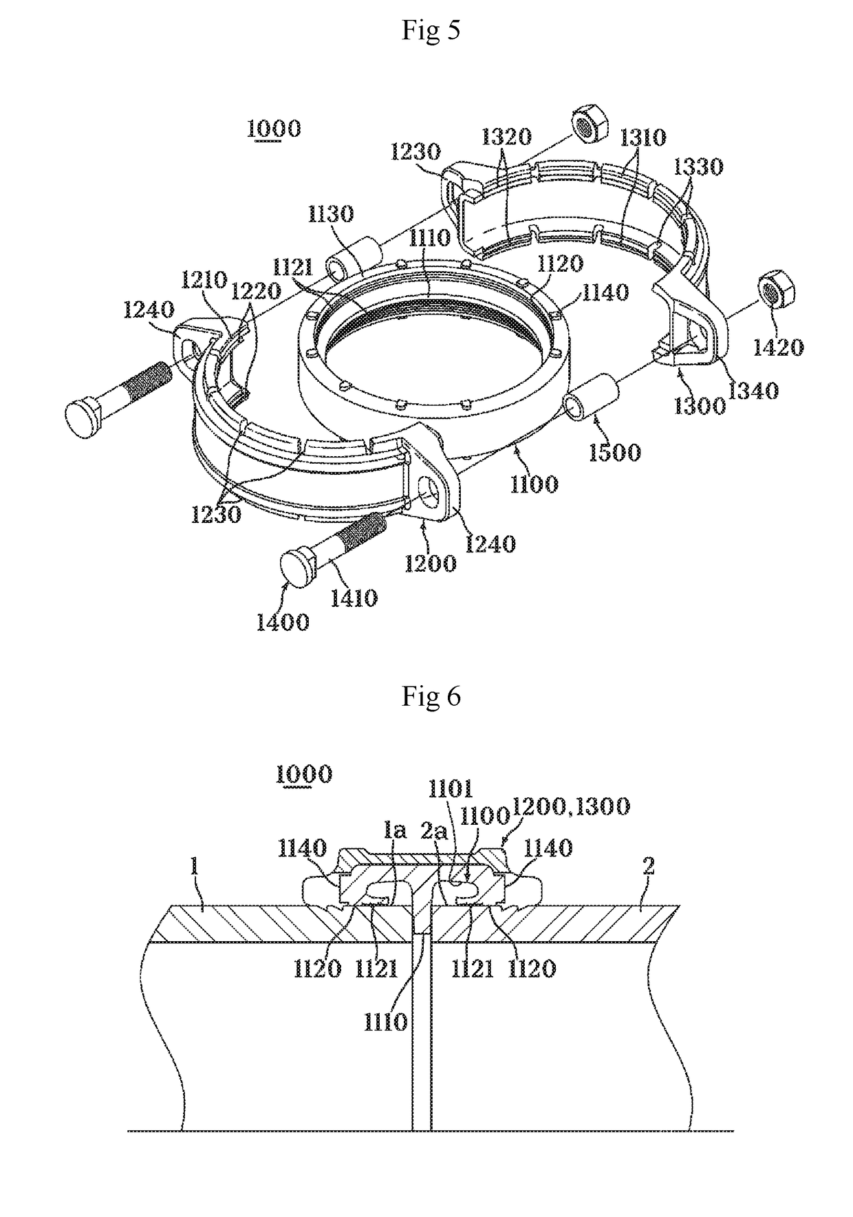
[0063]A seismic grooveless coupling 1000 according to the present invention, as shown in FIGS. 1 to 9, includes a packing 1100 formed of an elastic material into which pipes 1 and 2 that transfer fluid are separately inserted from left and right sides, upper and lower coupling segments 1200 and 1300 configured to surround the packing 1100 to be accommodated therein from upper and lower sides and restrict axial movements of the pipes 1 and 2 at both ends when getting closer to each other, and a bolt 1410 and a nut 1420 fastening the upper and lower coupling segments 1200 and 1300 each other.

[0064]In this case, the upper and lower coupling segments 1200 and 1300 include gripping parts 1220 and 1320 having a sawtooth-shape and formed at inner circumferential surface-center direction-both ends 1210 and 1310, and the gripping parts 1220 and 1320 are smaller than radiuses of the pipes 1 and 2 and have a hardness higher than those of the pipes 1 and 2.

[0065]Therefore, when the pipes 1 and ...

second embodiment

[0075]Hereinafter, a heat-treated gripping part for fixing, which is a main part of the second embodiment, will be described. The gripping part includes circle-shaped first grooves 1250 and 1350 which are inner circumferential surface-both ends 1210 and 1310 formed when the upper and lower coupling segments 1200 and 1300 are assembled and are formed in an axial center of the incised grooves 1230 and 1330, and a C-shaped gripping fixing ring 1600 inserted and mounted into the first grooves 1250 and 1350 and having a cut side. The gripping fixing ring 1600, which is a heat-treated stainless steel (SUS) series, has a sawtooth-shaped gripping surface 1610 formed on an inner circumferential surface thereof.

[0076]Therefore, gripping parts 1220 and 1320 according to a second embodiment are not configured to be integrated with the upper and lower coupling segments 1200 and 1300 as shown in the first embodiment and include the first grooves 1250 and 1350 and the C-shaped gripping fixing ring...

fourth embodiment

[0083]Hereinafter, the high pressure movable seismic grooveless coupling 1000 of the fourth embodiment further includes a circle-shaped press maintaining plate 1900 which is a backup ring and is formed between the inner circumferential-center direction-both ends 1210 and 1310 with the gripping parts 1220 and 1320 and both sides 1130 of the packing 1100, that is, between packing mounting grooves 1201 and 1301 in which the packing 1100 of the upper and lower coupling segments 1200 and 1300 is mounted.

[0084]When the circle-shaped press maintaining plate 1900 is inserted into the packing mounting grooves 1201 and 1301 and attached to both sides 1130 of the packing 1100, the packing 1100 does not need a incised groove-mounting protrusion 1140.

[0085]Therefore, when a high pressure fluid is supplied to the pipes 1 and 2, the circle-shaped press maintaining plate 1900 blocks the incised grooves 1230 and 1330 formed on the inner circumferential surface-center direction-both ends 1210 and 131...


PUM


Abstract

A seismic grooveless coupling is provided, which allows pipes to be connected by only pushing the pipes that do not have grooves on both sides thereof and fastening a bolt with a nut while the upper and lower coupling segments are assembled. The seismic grooveless coupling disclosed includes a packing made of an elastic material, wherein pipes transferring fluid are inserted into the packing from left and right sides, upper and lower coupling segments configured to restrict an axial movements of the pipes at both sides while surrounding the packing to be accommodated from upper and lower sides and getting closer to each other, and a fastening unit including a bolt and a nut configured to fasten the upper and lower coupling segments each other.

Description

CROSS-REFERENCE TO RELATED APPLICATIONS[0001]This application claims priority to PCT Application No. PCT / KR2016 / 013079 having a filing date of Nov. 14, 2016, based off of Korean Patent Application No. 10-2016-0110364 having a filing date of Aug. 29, 2016 and Korean Patent Application No. 10-2016-0089054 having a filing date of Jul. 14, 2016, the entire contents of all which are hereby incorporated by reference.FIELD OF TECHNOLOGY[0002]The following relates to a coupling and, more specifically, to a seismic grooveless coupling which allows fluid transport pipes or tubes to be connected without forming a groove at an end thereof when the fluid transport pipes or tubes are connected.BACKGROUND[0003]Generally, it has been institutionalized that many buildings have a sprinkler system for fire extinguishing. Also, it becomes more important to have the system for fire extinguishing in a residence.[0004]A regulation of a fire extinguishing tube system, such as a use of a fluid transport met...

Claims


Application Information

Patent Timeline
Patent Type & Authority Applications(United States)
IPC IPC(8): F16L17/06F16L21/06
CPCF16L17/06F16L21/06F16B2/12F16L17/04F16L21/005F16B2/06F16L21/065F16L21/08
Inventor NAM, SANG KEON
Owner NAM SANG KEON
Why Eureka
Try Eureka