Tool

a technology of fiber reinforced mesh and abrasive wheel, which is applied in the field of fiber reinforced mesh, can solve the problems of high speed and circumferential tensile of objects, and achieve the effects of reducing the cost of raw materials of fiber reinforced mesh or abrasive wheel, reducing the consumption of resin, and increasing spa

Inactive Publication Date: 2017-10-10
SAINT GOBAIN ABRASIVES INC +1
View PDF23 Cites 0 Cited by
  • Summary
  • Abstract
  • Description
  • Claims
  • Application Information

AI Technical Summary

Benefits of technology

[0023]An objective of the present invention is to provide a fiber reinforced mesh, which uses less resin materials to address the above deficiencies and problems present in the prior art. More importantly, it eliminates a long-standing technical prejudice by those skilled in the art, that is, the burst of the fiberglass reinforced mesh for bonding abrasive tools or abrasive wheels is related to the resin content of the reinforced mesh, and only a resin content higher than 90 g / m2, and the resin content of the reinforced mesh, and the resin content must be higher than 28%, to ensure the working functions including the toughness of the abrasive wheel and ensure a high burst speed of the abrasive wheel so as to conform to the safety standards.
[0024]Those skilled in the art have such a technical prejudice because: an abrasive wheel, especially a thin abrasive wheel, in high-speed cutting or grinding operation, will suffer a circumferential tensile stress as a result of the centrifugal force, and thus an object rotating at a high speed easily bursts. In order to improve the burst speed, the abrasive wheel must be provided with fiberglass coated with a resin layer, and these extendable fiberglass bundles can provide a crack bridging force to toughen the brittle abrasive substrate layer and hence reduce the crack tip stress in the abrasive substrate layer. As believed by those skilled in the art, after the fiberglass is coated with more than 90 g / m2 or about 40% of phenolic resin through dipping, a solid fiber / abrasive interfacial layer is formed between the fiberglass reinforced mesh and the abrasive substrate of the abrasive wheel after solidification as a result of such coating, which can reinforce the abrasive wheel and reduce the possibility of burst of the abrasive wheel rotating at a high speed.
[0025]However, the inventor of this present invention studied and found that there is no monotonic relationship between the burst speed of the abrasive wheel and the coating amount of phenolic resin, that is to say, a higher coating amount of resin does not mean a higher burst speed of the abrasive wheel; for the grinding ratio of the abrasive wheel, as shown by further test data, a small coating amount of resin only slightly reduces the grinding ratio of the abrasive wheel, which is still within the acceptable range of the requirements of grinding operation. Therefore, the coating amount of resin can be considerably reduced.

Problems solved by technology

Those skilled in the art have such a technical prejudice because: an abrasive wheel, especially a thin abrasive wheel, in high-speed cutting or grinding operation, will suffer a circumferential tensile stress as a result of the centrifugal force, and thus an object rotating at a high speed easily bursts.

Method used


Image

  • Tool
  • Tool
  • Tool

Examples


example 1

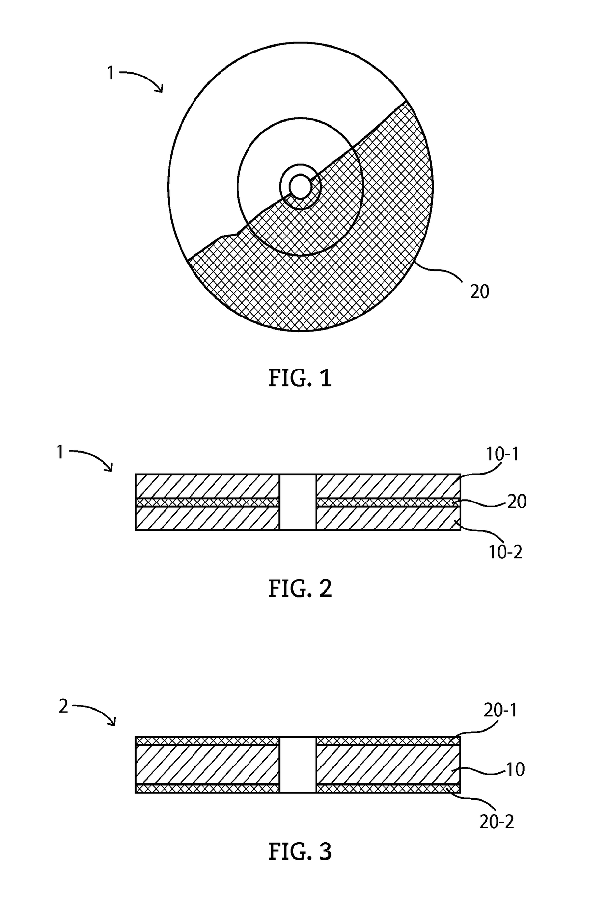
[0055]Firstly, cutting wheels with a size of 180×3×22 (mm) were tested. The structure of the cutting wheel is as shown in FIG. 3. The cutting wheel comprises a grinding layer 10 and two fiber reinforced mesh layers 20-1 and 20-2 are respectively provided on the upper and lower surfaces on the grinding layer 10. According to the specifications as set forth in a national standard of the People's Republic of China GB / T2485-2008 Technical Conditions for Bonding Abrasive Tools, the burst performance of an abrasive wheel shall be tested in accordance with a rotation test method on abrasive wheels as provided in a national standard of the People's Republic of China GB / T2493-1995 and shall conform to the related requirements.

[0056]Thus, the abrasive wheel of this embodiment was tested according to the national standard GB / T2493-1995, where the abrasive wheel was installed on a rotation testing machine (a POGGI rotation machine from Italy, type: PV22, maximum rotation speed: 22000 rpm) as sp...

example 2

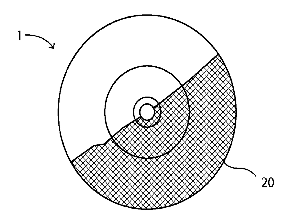
[0059]Cutting wheels with the same size of 180×3×22 (mm) were tested. The cutting wheels in Example 2 are different from those in Example 1 and the cross-sectional structure of this group of cutting wheels is shown in FIG. 2. The grinding layer of the cutting wheel is divided into a first grinding layer 10-1 and a second grinding layer 10-2, and the cutting wheel comprises a fiber reinforced mesh 20 between the first grinding layer and the second grinding layer. The tests include a rotation test and a grinding ratio measurement test. The conditions of the rotation test are the same as those in Example 1, and according to the tests, all tested cutting wheels passed the test and changes in the resin weight per unit area of the reinforced mesh did not affect the grinding ratio of the cutting wheel.

[0060]

TABLE 2Resin weight per unit area ofRotationGrindingfiber reinforced mesh (g / m2)testratio3.2Pass1.019.6Pass1.0316Pass1.0422.4Pass1.0228.8Pass1.0635.2Pass1.0641.9Pass1.0548Pass1.0456.9Pa...

example 3

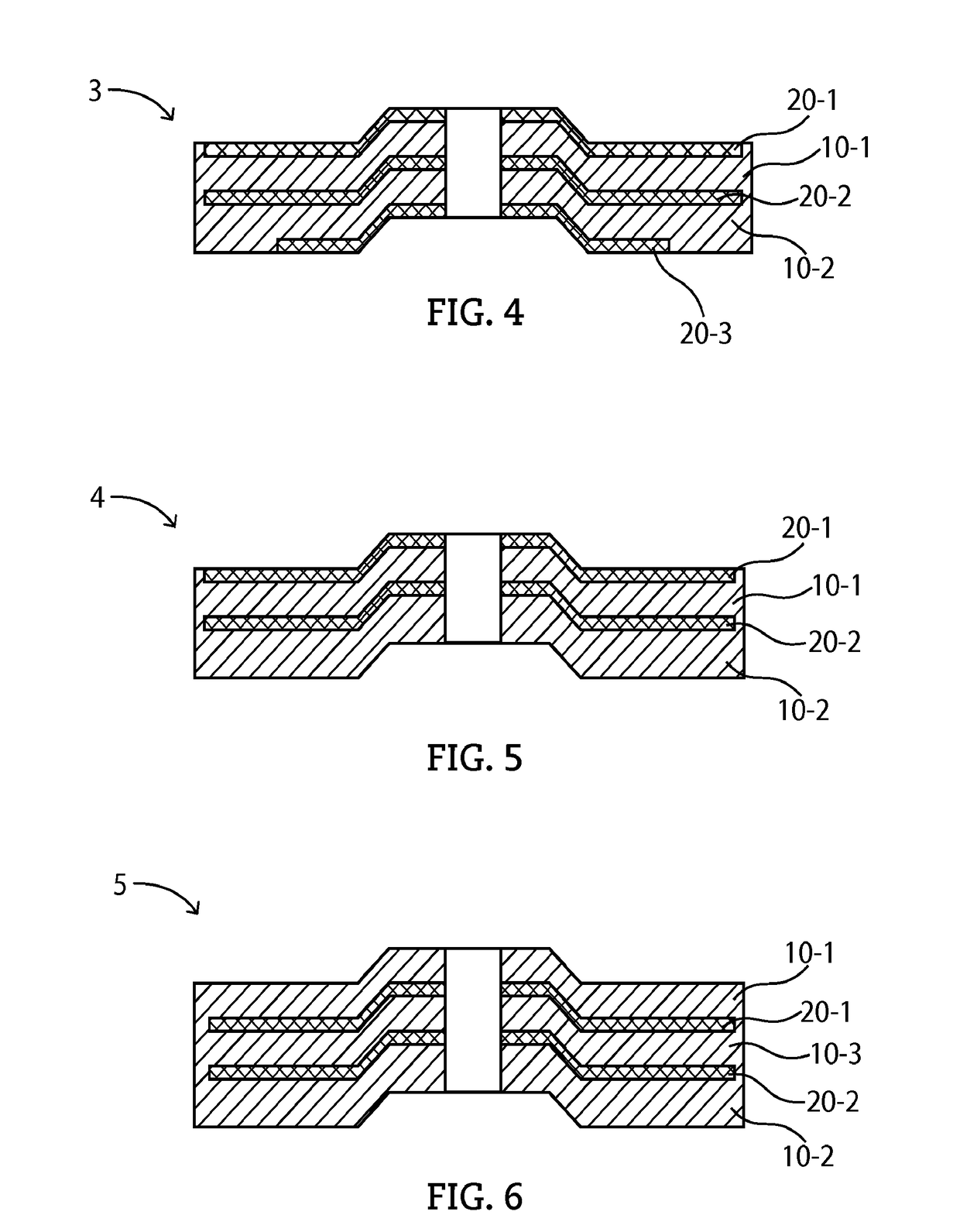
[0061]The inventor further tested angle grinding disks with a cross-sectional structure as shown in FIG. 4. The angle grinding disk has a size of 180×6×22 (mm), and comprises, along the direction as shown in FIG. 4 from top down, a first fiber reinforced mesh 20-1 overlaid on an upper surface of the grinding layer, a second fiber reinforced mesh 20-2 provided inside the grinding layer, and a third fiber reinforced mesh 20-3 partially overlaid on a lower surface of the grinding layer. The tests include a rotation test and a grinding ratio measurement test. The conditions of the rotation test are the same as those in Example 1. As shown in Table 3 hereinbelow, all the angle grinding disks passed the tests and changes in the resin weight per unit area of the fiber reinforced mesh did not affect the grinding ratio of the angle grinding disk.

[0062]

TABLE 3Resin weight per unit area ofRotationGrindingfiber reinforced mesh (g / m2)testratio3.2Pass11.99.6Pass12.516Pass12.322.4Pass12.428.8Pass1...


PUM


Abstract

The present invention discloses an improved tool, which comprises a reinforced member; and a resin layer is coated on the reinforced member, wherein the weight of the resin layer per unit area of the reinforced member may be less than 90 g / m2. The weight of the resin layer may be less than 15% of the total weight of the improved tool. The present invention dramatically reduces the production costs while maintaining the application performance unchanged.

Description

CROSS-REFERENCE TO RELATED APPLICATIONS[0001]This application is the National Stage of International Application No. PCT / US13 / 38009, entitled “AN IMPROVED TOOL”, by Dashi Nie et al., filed Apr. 24, 2013, which claims priority to Chinese Patent Application No. 201210126573.X, entitled “AN IMPROVED TOOL”, by Dashi Nie et al., filed Apr. 26, 2012 and Chinese Patent Application No. 201210126607.5, entitled “AN IMPROVED TOOL”, by Dashi Nie et al., filed Apr. 26, 2012, both of which are assigned to the current assignee hereof and incorporated herein by reference in their entireties.FIELD OF THE INVENTION[0002]The present invention relates to a reinforced substrate and an abrasive tool provided with the reinforced substrate, and more particularly to a fiber reinforced mesh for use in abrasive wheels, as well as a thin abrasive wheel comprising the fiber reinforced mesh.BACKGROUND OF THE INVENTION[0003]Bonding abrasive tools, which usually refer to abrasive wheels, generally consist of an a...

Claims


Application Information

Patent Timeline
Patent Type & Authority Patents(United States)
IPC IPC(8): B24D3/28B24D3/20B24D7/04B24D5/04
CPCB24D3/28B24D7/04B24D5/04B24D3/20
Inventor NIE, DASHIYU, XIANGBIN
Owner SAINT GOBAIN ABRASIVES INC
Why Eureka
Try Eureka