Tool
a technology of reinforced substrate and abrasive wheel, which is applied in the direction of gear teeth, gear teeth, application, etc., can solve the problems of high speed and circumferential tensile, and achieve the effects of reducing the cost of raw materials of fiber reinforced mesh or abrasive wheel, reducing the consumption of resin, and increasing spa
- Summary
- Abstract
- Description
- Claims
- Application Information
AI Technical Summary
Benefits of technology
Problems solved by technology
Method used
Image
Examples
example 1
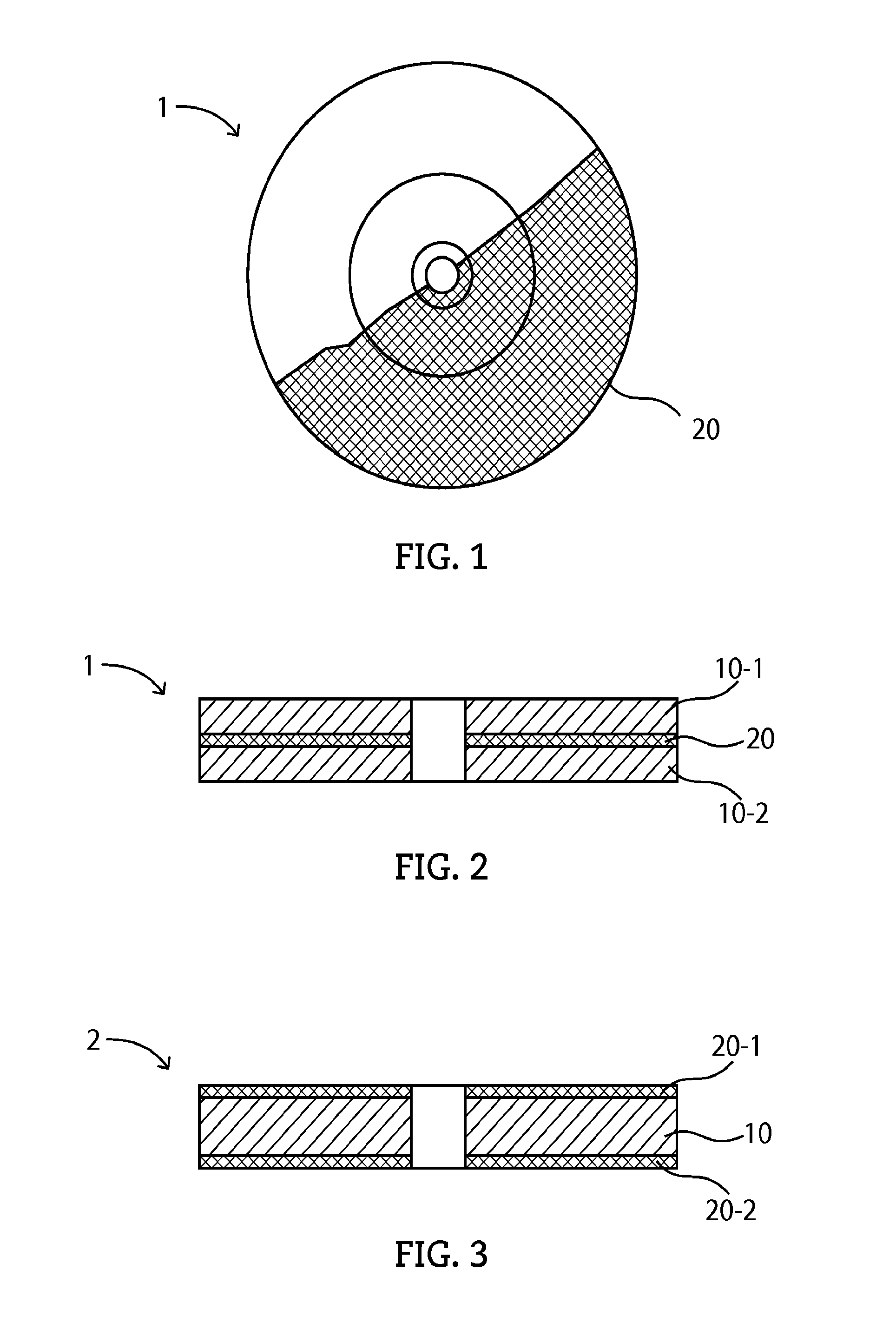
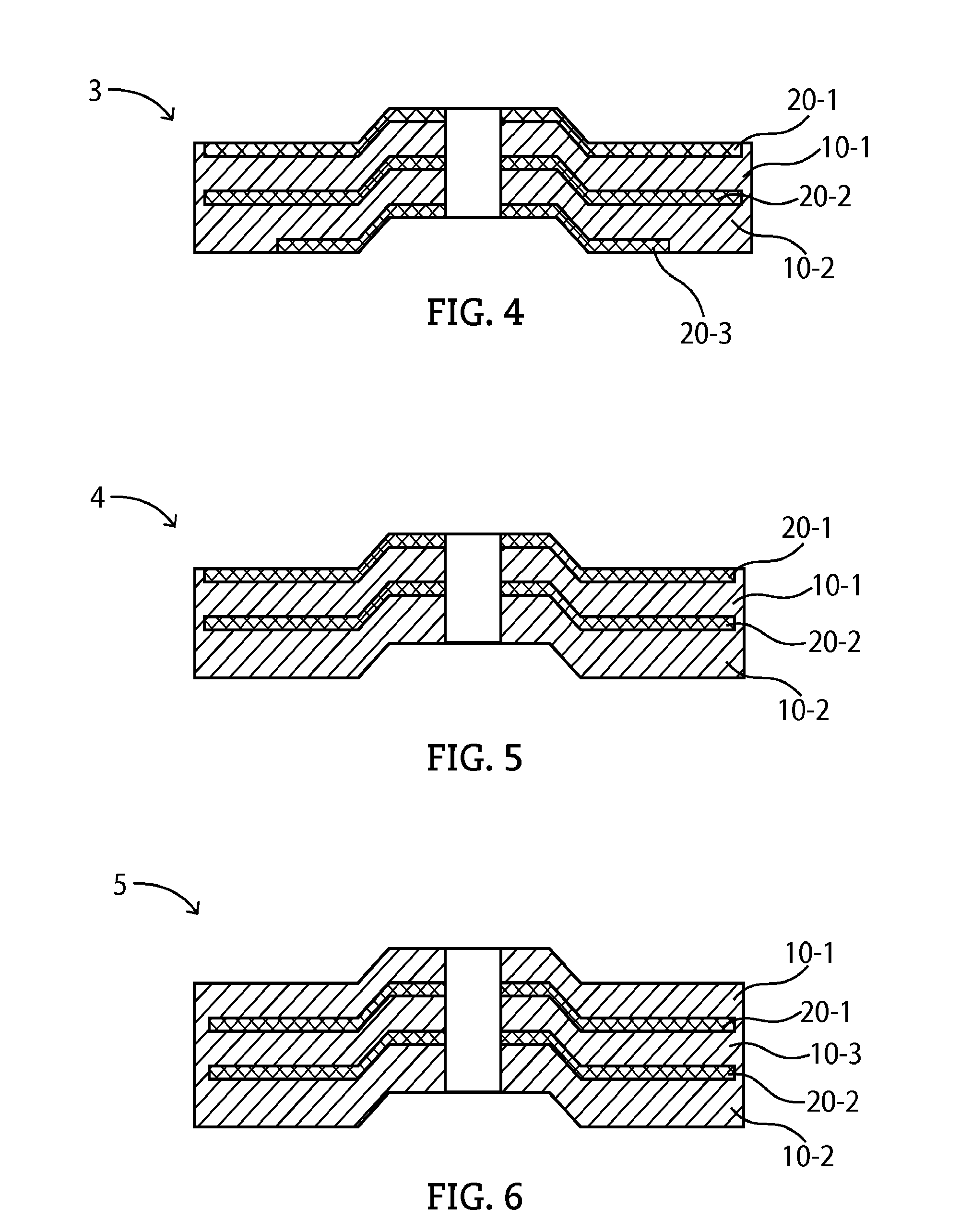
[0051]Firstly, cutting wheels with a size of 180×3×22 (mm) were tested. The structure of the cutting wheel is as shown in FIG. 3. The cutting wheel comprises a grinding layer 10 and two fiber reinforced mesh layers 20-1 and 20-2 are respectively provided on the upper and lower surfaces on the grinding layer 10. According to the specifications as set forth in a national standard of the People's Republic of China GB / T2485-2008 Technical Conditions for Bonding Abrasive Tools, the burst performance of an abrasive wheel shall be tested in accordance with a rotation test method on abrasive wheels as provided in a national standard of the People's Republic of China GB / T2493-1995 and shall conform to the related requirements.
[0052]Thus, the abrasive wheel of this embodiment was tested according to the national standard GB / T2493-1995, where the abrasive wheel was installed on a rotation testing machine (a POGGI rotation machine from Italy, type: PV22, maximum rotation speed: 22000 rpm) as sp...
example 2
[0054]Cutting wheels with the same size of 180×3×22 (mm) were tested. The cutting wheels in Example 2 are different from those in Example 1 and the cross-sectional structure of this group of cutting wheels is shown in FIG. 2. The grinding layer of the cutting wheel is divided into a first grinding layer 10-1 and a second grinding layer 10-2, and the cutting wheel comprises a fiber reinforced mesh 20 between the first grinding layer and the second grinding layer. The tests include a rotation test and a grinding ratio measurement test. The conditions of the rotation test are the same as those in Example 1, and according to the tests, all tested cutting wheels passed the test and changes in the resin weight per unit area of the reinforced mesh did not affect the grinding ratio of the cutting wheel.
TABLE 2Resin weight per unit area ofRotationGrindingfiber reinforced mesh (g / m2)testratio3.2Pass1.019.6Pass1.0316Pass1.0422.4Pass1.0228.8Pass1.0635.2Pass1.0641.9Pass1.0548Pass1.0456.9Pass1.03...
example 3
[0055]The inventor further tested angle grinding disks with a cross-sectional structure as shown in FIG. 4. The angle grinding disk has a size of 180×6×22 (mm), and comprises, along the direction as shown in FIG. 4 from top down, a first fiber reinforced mesh 20-1 overlaid on an upper surface of the grinding layer, a second fiber reinforced mesh 20-2 provided inside the grinding layer, and a third fiber reinforced mesh 20-3 partially overlaid on a lower surface of the grinding layer. The tests include a rotation test and a grinding ratio measurement test. The conditions of the rotation test are the same as those in Example 1. As shown in Table 3 hereinbelow, all the angle grinding disks passed the tests and changes in the resin weight per unit area of the fiber reinforced mesh did not affect the grinding ratio of the angle grinding disk.
TABLE 3Resin weight per unit area ofRotationGrindingfiber reinforced mesh (g / m2)testratio3.2Pass11.99.6Pass12.516Pass12.322.4Pass12.428.8Pass12.435....
PUM
 Abstract
Description
Claims
Application Information
 - R&D
- Intellectual Property
- Life Sciences
- Materials
- Tech Scout
- Unparalleled Data Quality
- Higher Quality Content
- 60% Fewer Hallucinations
Browse by: Latest US Patents, China's latest patents, Technical Efficacy Thesaurus, Application Domain, Technology Topic, Popular Technical Reports.
© 2025 PatSnap. All rights reserved.Legal|Privacy policy|Modern Slavery Act Transparency Statement|Sitemap|About US| Contact US: help@patsnap.com


