Gas supply device and method for starting operation of gas supply device

a gas supply device and gas supply technology, applied in the direction of electrochemical generators, container discharging methods, container filling under pressure, etc., can solve the problem of prolonged activation time, and achieve the effect of reducing the time required for activation of gas stations

Active Publication Date: 2019-03-21
KOBE STEEL LTD
View PDF15 Cites 8 Cited by
  • Summary
  • Abstract
  • Description
  • Claims
  • Application Information

AI Technical Summary

Benefits of technology

[0004]An object of the present invention is to provide a gas supply device capable of reducing the time required for activating the gas station and a method for starting an operation of the gas supply device.

Problems solved by technology

However, when activating the hydrogen station by such a method, there is a concern that time required for the activation is prolonged because it takes time for the refrigerator to cool the refrigerant.

Method used


Image

  • Gas supply device and method for starting operation of gas supply device
  • Gas supply device and method for starting operation of gas supply device
  • Gas supply device and method for starting operation of gas supply device

Examples


first embodiment

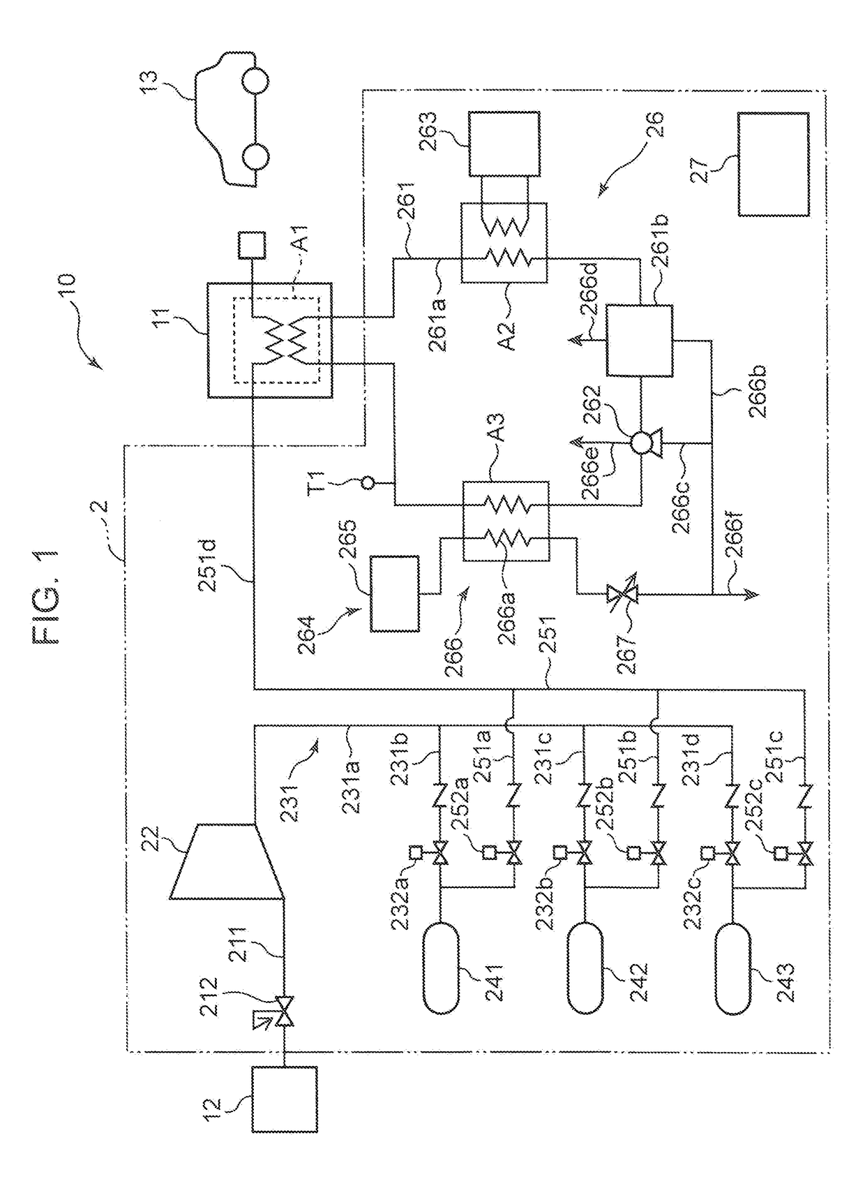
[0017]FIG. 1 is a diagram schematically illustrating a configuration of a hydrogen station 10 according to a first embodiment of the present invention. The hydrogen station 10 includes a gas supply device 2 and a dispenser 11, which is a charging facility.

[0018]The gas supply device 2 compresses a hydrogen gas to generate a compressed gas, and supplies the compressed gas to the dispenser 11. In the present embodiment, as illustrated in FIG. 1, the hydrogen gas produced in a gas production device 12 is supplied to the gas supply device 2, and the gas supply device 2 compresses the hydrogen gas to generate the compressed gas.

[0019]Note that a supply source for supplying the hydrogen gas to the gas supply device 2 may not be the gas production device 12. For example, the hydrogen gas may be supplied from a tank member storing the hydrogen gas to the gas supply device 2.

[0020]In the present embodiment, since the gas supply device 2 is a component of the hydrogen station 10, the gas prod...

second embodiment

[0074]Next, a gas supply device 2 according to a second embodiment will be described with reference to FIG. 4. Note that the present embodiment will describe only portions different from the first embodiment, and descriptions of the same structure, operation, and effect as those of the first embodiment will be omitted.

[0075]In the second embodiment, a configuration of a hydrogen station 10 is similar to the configuration of the hydrogen station 10 of the first embodiment, but the second embodiment is different from the first embodiment in a method for operating the hydrogen station 10.

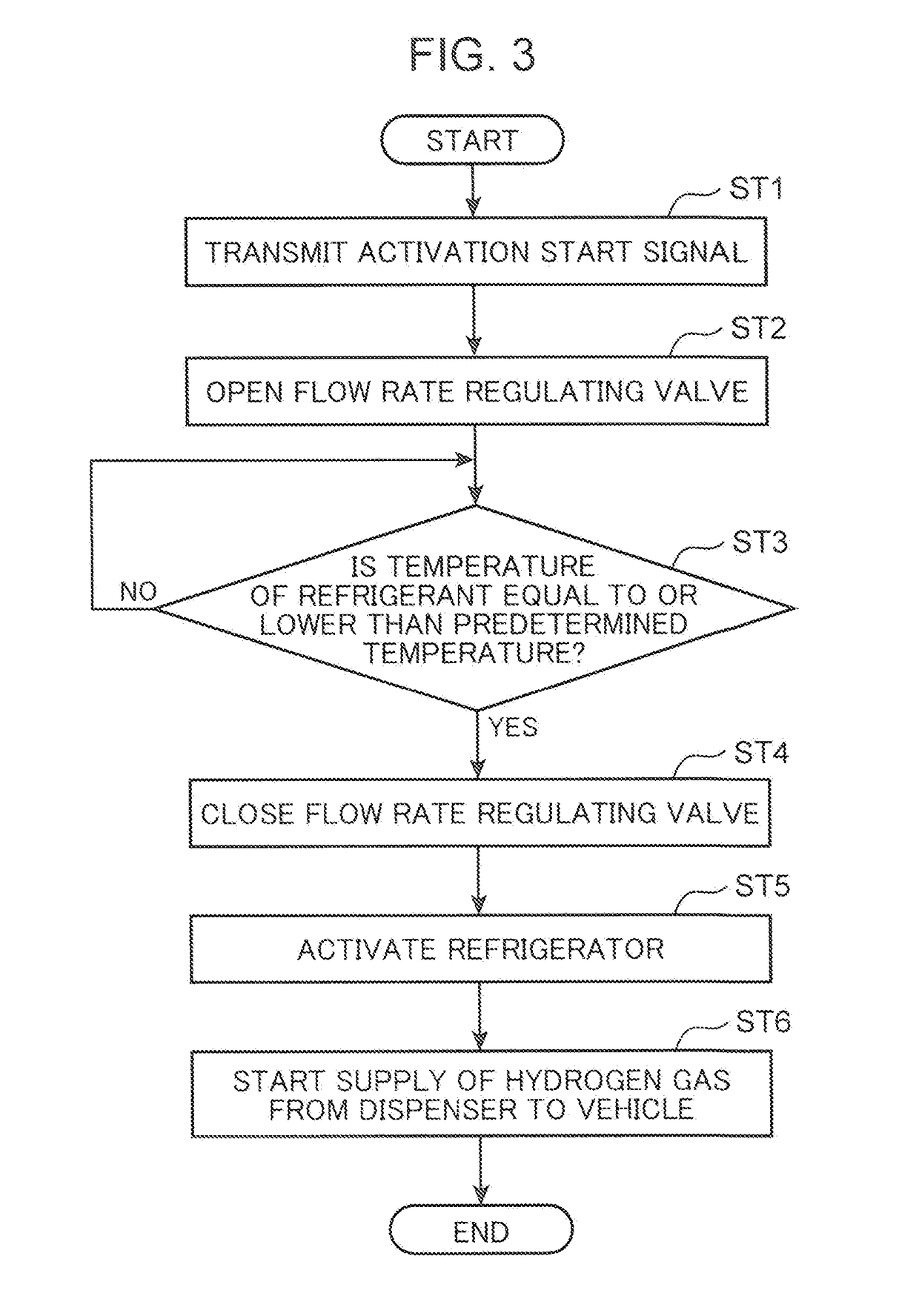
[0076]In the second embodiment, as illustrated in FIG. 4, upon receipt of an activation start signal transmitted in step ST1, while opening a flow rate regulating valve 267 (step ST2), a control unit 27 performs control to activate a refrigerator 263 (step ST5). Accordingly, a refrigerant flowing through a refrigerant flow path 261 is cooled by the refrigerator 263 and is also cooled by latent heat of ...

third embodiment

[0082]Next, a gas supply device 2 according to a third embodiment will be described with reference to FIGS. 5 and 6. Note that the present embodiment will describe only portions different from the first embodiment, and descriptions of the same structure, operation, and effect as those of the first embodiment will be omitted.

[0083]In the third embodiment, a structure of a cooling device 264 is different from a configuration of a cooling device 264 in the first embodiment.

[0084]In the third embodiment, the cooling device 264 includes a liquefied gas tank 265, a liquefied gas flow path 268, and a flow rate regulating valve 267. The liquefied gas flow path 268 introduces liquid nitrogen stored in the liquefied gas tank 265 into a refrigerant tank 261b to cool a refrigerant in the refrigerant tank 261b.

[0085]Specifically, as illustrated in FIGS. 5 and 6, the liquefied gas flow path 268 includes an introduction side flow path 268a, an intra-tank flow path 268b, and a lead-out side flow p...


PUM


Abstract

A gas supply device for supplying a hydrogen gas to a dispenser of a hydrogen station includes: a refrigerant flow path through which a refrigerant for cooling the gas before being discharged from the dispenser flows; a refrigerator that can cool the refrigerant; a cooling device that can cool the refrigerant by latent heat when liquid hydrogen changes to the hydrogen gas; and a control unit that performs control to activate the refrigerator while stopping the cooling device when a condition set in advance is satisfied after performing control to activate the cooling device in activation of the hydrogen station.

Description

FIELD OF THE INVENTION[0001]The present invention relates to a gas supply device for supplying a gas to a dispenser of a gas station, and a method for starting an operation of the gas supply device.BACKGROUND ART[0002]In recent years, vehicles using a hydrogen gas such as fuel cell vehicles and hydrogen vehicles have been developed. As such vehicles are developed, hydrogen stations for charging a tank of the vehicle with a hydrogen gas are becoming increasingly common. As one example of such a hydrogen station, Japanese Patent Application Laid-Open No. 2015-158213 describes a hydrogen station including a gas supply system for supplying a hydrogen gas and a dispenser for supplying the hydrogen gas supplied from the gas supply system to a tank of a vehicle according to a predetermined protocol. Such a hydrogen station needs to supply the hydrogen gas discharged from the dispenser to the tank of the vehicle with the hydrogen gas being cooled to a predetermined temperature. Therefore, t...

Claims


Application Information

Patent Timeline
Patent Type & Authority Applications(United States)
IPC IPC(8): F17C5/00B60K15/067F17C5/06B60S5/02
CPCF17C5/007B60K15/067F17C5/06B60S5/02B60K2015/03315F17C2221/012F17C2221/013F17C2221/033F17C2227/0135F17C2227/0157F17C2227/0355F17C2265/065F17C2270/0139F17C13/026F17C2227/046F17C2201/056F17C2223/0123F17C2223/036F17C2225/0123F17C2225/036F17C2270/0178F17C2270/0184Y02P90/45F17C5/04F17C13/04F17C2227/0339F17C2250/0439F17C2250/0689F17C2270/0168
Inventor FUJISAWA, AKITOSHINAGURA, KENJI
Owner KOBE STEEL LTD
Why Eureka
Try Eureka