Electrical connection device in an aircraft

a technology of electrical connection and aircraft, which is applied in the direction of electrically conductive connections, coupling device connections, vehicle connectors, etc., can solve the problems of low electrical conductivity, poor withstanding heating, carbon and/or composite materials that now replace metal structures, etc., to reduce the number of assembly elements, facilitate the making of electrical connections, and reduce the time

Active Publication Date: 2019-03-21
SAFRAN ELECTRICAL & POWER
View PDF0 Cites 1 Cited by
  • Summary
  • Abstract
  • Description
  • Claims
  • Application Information

AI Technical Summary

Benefits of technology

[0008]An object of the present invention is to remedy the above-mentioned drawbacks. More precisely, the present invention seeks in particular to facilitate making electrical connections between electric cables and electrically conductive structures, to reduce the time required for preparing and assembling such electrical connections, to reduce the number of assembly elements that are used, and to limit the risk of losing or forgetting electrically conductive foreign bodies.

Problems solved by technology

The structures made of carbon and / or composite materials that now replace metal structures present low electrical conductivity and are poor at withstanding heating produced by Joule effects.
Specifically, if the torque is not sufficient, then the quality of the electrical contact between the terminal lug 11 and the electrically conductive structure 13, which is coupled to the vibration of the aircraft, will lead to an increase in contact electrical resistance, leading to an undesired rise in temperature.
Conversely, if the clamping is excessive, there is then a risk of the conductive material suffering creep, which is harmful to the quality of the electrical contact.
Furthermore, during assembly or maintenance of electrical connections, there is a risk of electrically conductive foreign bodies (e.g. assembly tools, screws, nuts) dropping, being lost, or forgotten in the aircraft.
This risk can lead to two different electrical polarities being put into contact, thereby giving rise to a short circuit and an electric arc.

Method used


Image

  • Electrical connection device in an aircraft
  • Electrical connection device in an aircraft
  • Electrical connection device in an aircraft

Examples


first embodiment

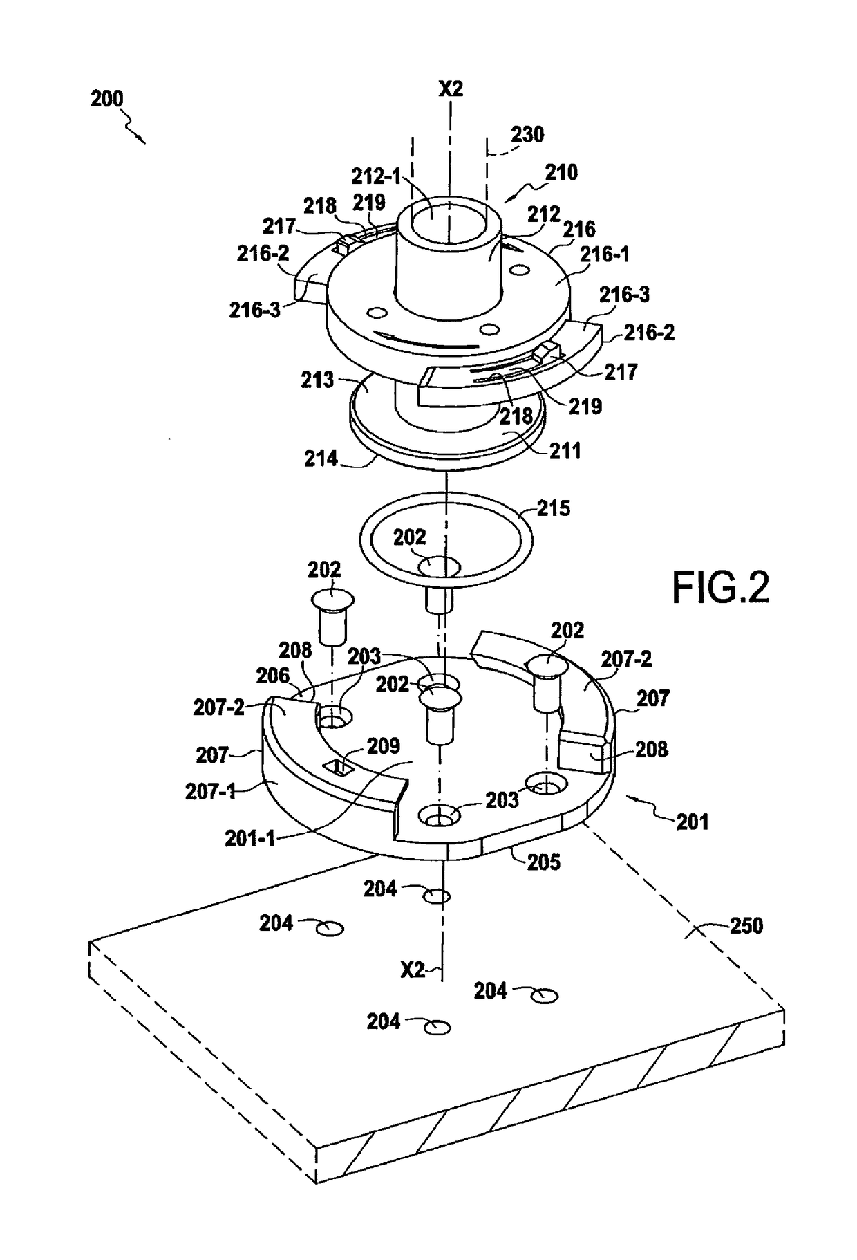
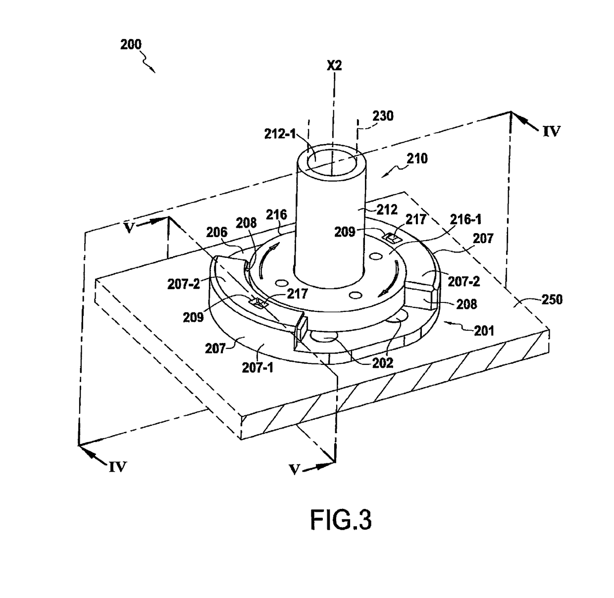
[0047]FIGS. 2 to 5 show an electrical connection device 200 in the invention. In the example shown, the device 200 is centered relative to an axis of revolution X2 that is formed by a support 201 and by a terminal lug 210.

[0048]The support 201 is to be fastened to an electrically conductive structure 250, e.g. a metal structure of an aircraft. All or part of the support 201 is electrically conductive, in particular a bottom face of the support 201 that is to be fastened to the electrically conductive structure 250. The support 201 is fastened to the structure 250 by using permanent fastener elements 202, e.g. using rivets with countersunk or round heads, and passing in succession through fastener orifices 203, 204 formed respectively in the support 201 and the electrically conductive structure 250.

[0049]Below the term “bottom” is used to designate any face facing towards the structure 250, and the term “top” is used to designate any face facing away from the structure 250.

[0050]The ...

second embodiment

[0066]FIGS. 6 to 8 show an electrical connection device 300 in the invention. In the example shown, the device 300 is centered relative to an axis of revolution X3 and it is formed by a support 301 and a terminal lug 310, the support 301 being for fastening to an electrically conductive structure 350, e.g. a metal surface of an aircraft.

[0067]Below, the term “bottom” is used to designate any face facing towards the structure 350, and the term “top” is used to designate any face facing away from the structure 350.

[0068]The support 301 has a first face 302 (bottom face) that is to come into contact with the structure 350, and a second face 303 opposite from the first face 302, i.e. a top face. At least two locking clips 304 project from the second face 303 of the support 301 and define between them a housing 305 for receiving a bottom face of the terminal lug 310. In the example shown, the locking clips 304 are arranged in three sets 306 of three clips each. The sets 306 being regular...

third embodiment

[0081]FIGS. 9 and 10 show an electrical connection device 400 in the invention. The device 400 is constituted by a support 401 and a terminal lug 410, the support 401 being for fastening on an electrically conductive structure 450, e.g. a metal surface of an aircraft.

[0082]Below the term “bottom” is used to designate any face facing towards the structure 450, and the term “top” is used to designate any face facing away from the structure 450.

[0083]The support 401 has a first face 402 (bottom face) that is to come into contact with the structure 450, and a second face 403 opposite from the first face 402, i.e. a top face. An elastically deformable shoe 404 and at least one elastically deformable locking tongue 405 project from the second face 403, defining between them a housing 406, and they extend towards the inside of the housing 406. In the example shown, the support 401 has two locking tongues 405 projecting from the top face of the support 401.

[0084]The support 401 also has fas...


PUM


Abstract

An electrical connection device including a support and an electrically conductive terminal lug, wherein the support includes a first face, with channels projecting from a second face opposite from the first face and defining between them a housing; the terminal lug includes a base for placing in the housing and a shank fastened coaxially to the base, the base including a first face from which the shank extends and a second face opposite from the first face for coming to bear against the second face of the support; the terminal lug including a locking ring having the shank passing through its center and movable in rotation relative to the shank, the ring including ramps extending from the outer periphery of the ring, the ramps co-operating with the channels.

Description

BACKGROUND OF THE INVENTION[0001]The invention relates to an electrical connection device for fastening to an electrically conductive structure and for being electrically connected to an electric cable. An application of the invention may lie with interconnecting electrical return circuits, in particular on board aircraft.[0002]In modern aircraft, more and more metal structures are being replaced by carbon and / or composite structures, in particular in the fuselage. In the past, the metal structures of aircraft provided the functional electrical return for electrical equipment by grounding the equipment, enabled the conductive housings of electrical equipment to be bonded, enabled all of the non-electrical metal parts to be set to the same potential, provided electromagnetic compatibility (EMC) protection for electrical installations, and served to convey direct or indirect currents due to lightning.[0003]The structures made of carbon and / or composite materials that now replace metal...

Claims


Application Information

Patent Timeline
Patent Type & Authority Applications(United States)
IPC IPC(8): H01R11/12H01R11/26H01R4/30H01R13/625H01R4/00H01R4/38
CPCH01R11/12H01R11/26H01R4/30H01R13/625H01R4/54H01R4/38H01R13/5202H01R4/28H01R11/11H01R13/20H01R2201/26
Inventor BLINEAU, JEAN MARCCOLIN, FREDERIC
Owner SAFRAN ELECTRICAL & POWER
Why Eureka
Try Eureka