Blade set manufacturing method, blade set and hair cutting appliance

a manufacturing method and technology for hair cutting appliances, applied in metal working devices and other directions, can solve the problems of skin damage, adverse effects, and certain remaining assembly tolerances that cannot be avoided in common manufacturing and design approaches, and achieve the effect of improving the operational performance of respective equipped hair cutting appliances, reducing the number of required components and assembly steps, and steady level of performan

Active Publication Date: 2019-03-28
KONINKLJIJKE PHILIPS NV
View PDF24 Cites 2 Cited by
  • Summary
  • Abstract
  • Description
  • Claims
  • Application Information

AI Technical Summary

Benefits of technology

[0009]It is an object of the present disclosure to provide a method of manufacturing a blade set that tackles at least some of the above discussed issues and that preferably enables a high-precision assembling of blade sets which preferably results in an improved operational performance of a respectively equipped hair cutting appliance. Preferably, the manufacturing method enables to assemble the blade set without huge additional manufacturing efforts. Further, it is desirable to present a blade set assembly method which enables a further reduction of the number of required components and assembly steps. Preferably, blade sets that have been assembled in accordance with the manufacturing method are durable and arranged to be operated at a steady level of performance for a long time. Furthermore, it is desired that no additional adjustment and / or calibration efforts are required at the level of the end user.

Problems solved by technology

Hence, tip-to-tip adjustment often involves a tradeoff between sufficient precision and the likelihood of skin damage.
This method has several drawbacks at least some of which are attributable to a resulting remaining tolerance range which may have adverse effects on the above design goals.
Due to a lack of precision at the single component level and at the manufacturing stage, and due to some inherent inconsistency in the adjustment procedure, a certain level of remaining assembly tolerances cannot be avoided in accordance with common manufacturing and design approaches.
However, this involves certain tasks to be performed by the end user and therefore complicates the operation of hair cutting appliances.

Method used


Image

  • Blade set manufacturing method, blade set and hair cutting appliance
  • Blade set manufacturing method, blade set and hair cutting appliance
  • Blade set manufacturing method, blade set and hair cutting appliance

Examples


Embodiment Construction

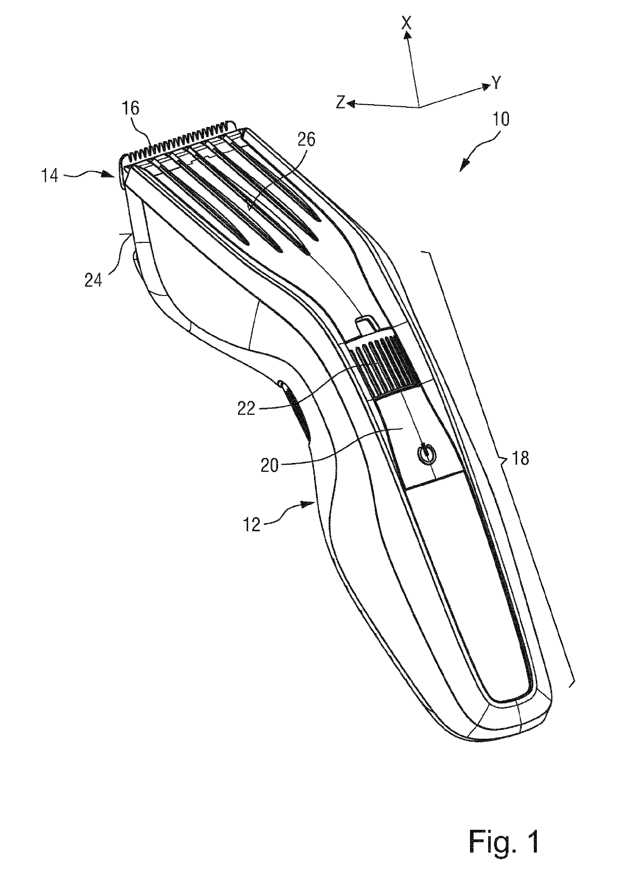
[0089]FIG. 1 shows a schematic perspective rear view of a hair cutting appliance 10, particularly an electrically operated hair cutting appliance 10. The appliance 10 may also be referred to as hair clipper or hair trimmer. The appliance 10 comprises a housing or housing portion 12 having a generally elongated shape. At a first, top end thereof, a cutting head 14 is provided. The cutting head 14 comprises a blade set assembly 16. The blade set assembly 16 comprises a movable blade and a stationary blade (refer to FIG. 3) that may be moved with respect to each other to cut hair. At a central portion and a second, bottom end of the housing 12, a handle or grip portion 18 is formed. A user may grasp or grab the housing 12 at the grip portion 18.

[0090]The appliance 10 in accordance with the exemplary embodiment of FIG. 1 further comprises operator controls. For instance, an on-off switch or button 20 may be provided. Furthermore, in case the appliance 10 is provided with a comb length a...


PUM


Abstract

The present disclosure relates to method of manufacturing a blade set assembly (16), a blade set assembly (16), and to a hair cutting appliance (10). The method comprising the steps of providing a base component (32) comprising a stationary blade (34), providing a movable component (50) comprising a cutter blade (52), providing a coupling element (62), the coupling element (62) being arranged to be interposed between the base component (32) and the movable component (50), providing a plastic contact bridge (54), arranging the stationary blade (34) and the cutter blade (52) at a defined relative assembly position, securing the assembly position between the stationary blade (34) and the cutter blade (52), involving attaching the plastic contact bridge (54) to one of the base component (32) and the movable component (50), attaching a retaining portion (64) of the coupling element (62) to the other one of the base component (32) and the movable component (50), and penetrating the plastic contact bridge (54) with at least one insertion end (74, 76) of the coupling element (62).

Description

FIELD OF THE INVENTION[0001]The present disclosure relates to a method of manufacturing a blade set assembly for a hair cutting appliance, to a blade set assembly, and to a hair cutting appliance implementing such a blade set assembly.[0002]More particularly, the present disclosure relates to improvements in hair cutting devices wherein the cutting action is obtained by reciprocating blades, such as clippers and trimmers. More specifically, the present disclosure relates to novel approaches to obtaining an optimal spacing between blades in hair cutting appliances comprising a blade set arrangement involving a movable cutter blade (also referred to as cutter) and a stationary blade (also referred to as guard).BACKGROUND OF THE INVENTION[0003]Hair cutting appliances, particularly electric hair cutting appliances, are generally known and may include trimmers, clippers and shavers, for instance. Electric hair cutting appliances may also be referred to as electrically powered hair cuttin...

Claims


Application Information

Patent Timeline
Patent Type & Authority Applications(United States)
IPC IPC(8): B26B19/06B26B19/38
CPCB26B19/06B26B19/3846B26B19/3893B26B19/20
Inventor HOEXUM, EVERHARDUS JOHANNESMAAT, WILLEMSABLATSCHAN, SIEGFRIEDSTAPELBROEK, MARTINUS BERNARDUSRETHMEIER, ROEL ALEXANDERGEERT-JANAITINK, ALBERT JANBERNTSEN, LUCGOSENSHUIS, DAAN HENDRIK
Owner KONINKLJIJKE PHILIPS NV
Why Eureka
Try Eureka