Control system for work vehicle, control method, and work vehicle

a control system and work vehicle technology, applied in image analysis, image enhancement, constructions, etc., can solve the problems of poor quality of finished work, difficult to perform desirable filling work under, difficult to compact piled soil, etc., to achieve easy compacting, improve work efficiency, and improve the effect of finished work quality

Active Publication Date: 2019-03-28
KOMATSU LTD
View PDF18 Cites 9 Cited by
  • Summary
  • Abstract
  • Description
  • Claims
  • Application Information

AI Technical Summary

Benefits of technology

[0007]An object of the present invention is to provide a control system for a work vehicle, a control method, and a work vehicle that enable filling work to be performed that is efficient and exhibits a quality finish using automatic controls.
[0012]According to the present invention, a work implement is automatically controlled so as to move to a position above the actual topography. At this time, the work implement is moved to a position below the final design topography whereby soil can be piled thinly on the actual topography in comparison to a case of moving the work implement along a final design topography. As a result, the piled up soil can be easily compacted by the work vehicle. Accordingly, the quality of the finished work can be improved. Moreover, work efficiency can be improved.

Problems solved by technology

However, it is difficult to perform desirable filling work under the abovementioned automatic controls.
In this case, it is difficult to compact the piled soil because the thickness of the piled soil is too large.
As a result, there is a problem that the quality of the finished work is poor.
In this case, there is a problem that the efficiency of the work is poor.

Method used


Image

  • Control system for work vehicle, control method, and work vehicle
  • Control system for work vehicle, control method, and work vehicle
  • Control system for work vehicle, control method, and work vehicle

Examples


Embodiment Construction

)

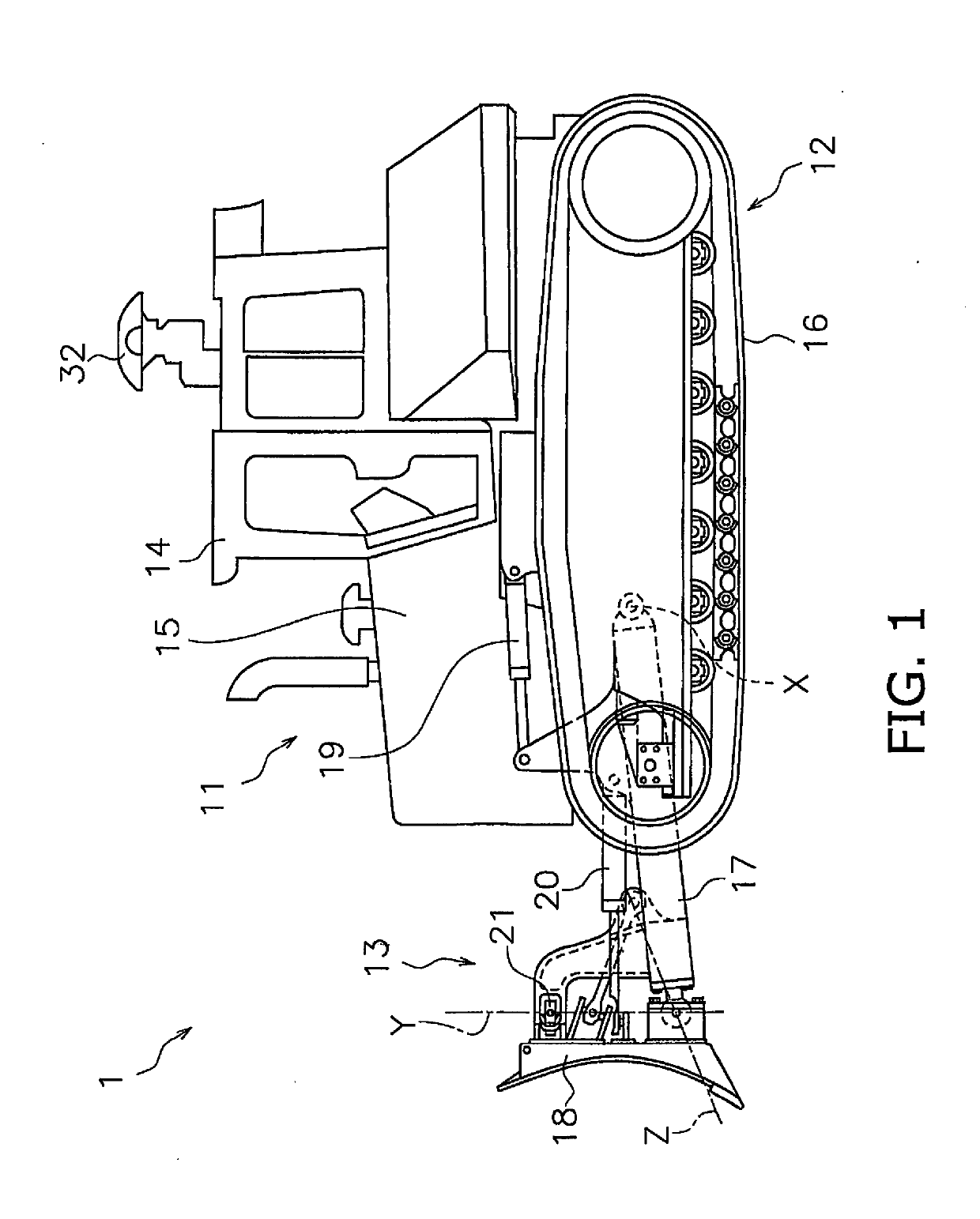
[0033]A work vehicle according to an embodiment will be explained in detail with reference to the drawings. FIG. 1 is a side view of the work vehicle 1 according to an embodiment. The work vehicle 1 is a bulldozer according to the present embodiment. The work vehicle 1 is provided with a vehicle body 11, a travel device 12, and a work implement 13.

[0034]The vehicle body 11 has an operating cabin 14 and an engine compartment 15. An operator's seat that is not illustrated is disposed inside the operating cabin 14. The engine compartment 15 is disposed in front of the operating cabin 14. The travel device 12 is attached to a bottom part of the vehicle body 11. The travel device 12 has a pair of left and right crawler belts 16. Only the right crawler belt 16 is depicted in FIG. 1. The work vehicle 1 travels due to the rotation of the crawler belts 16.

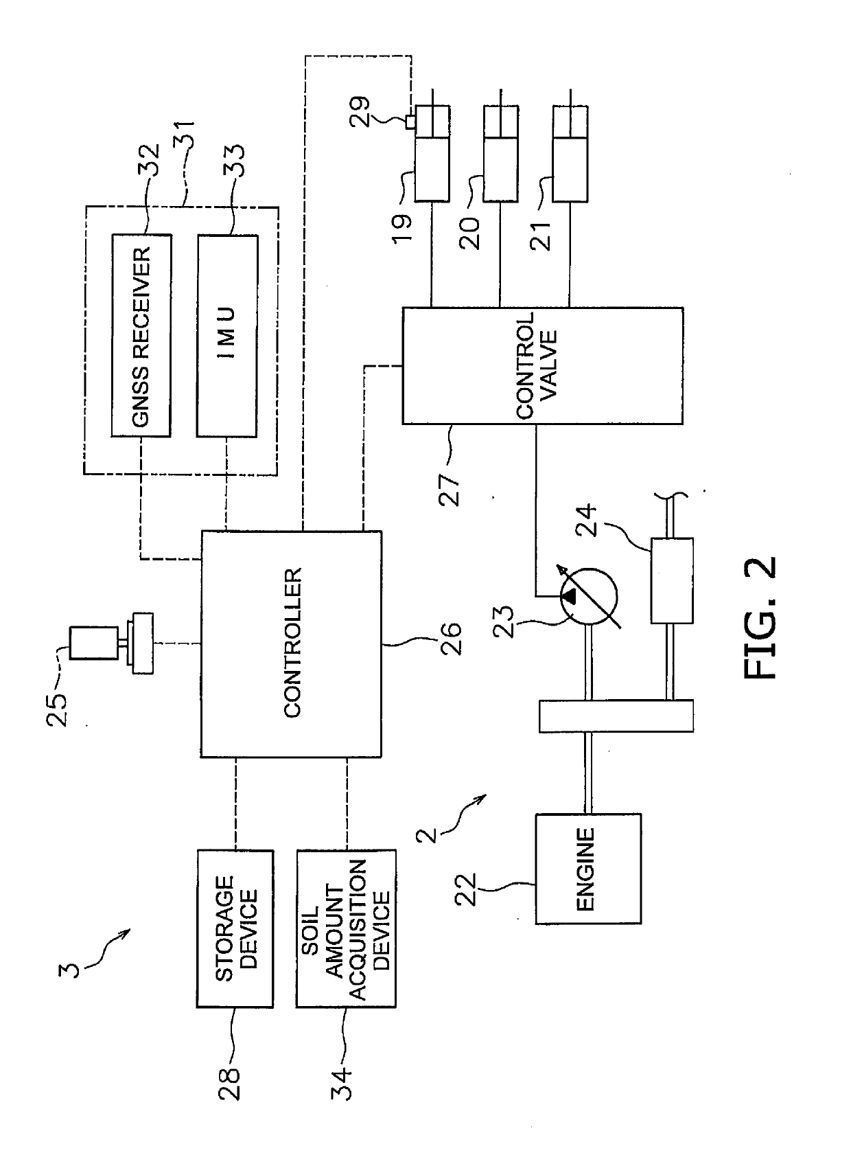
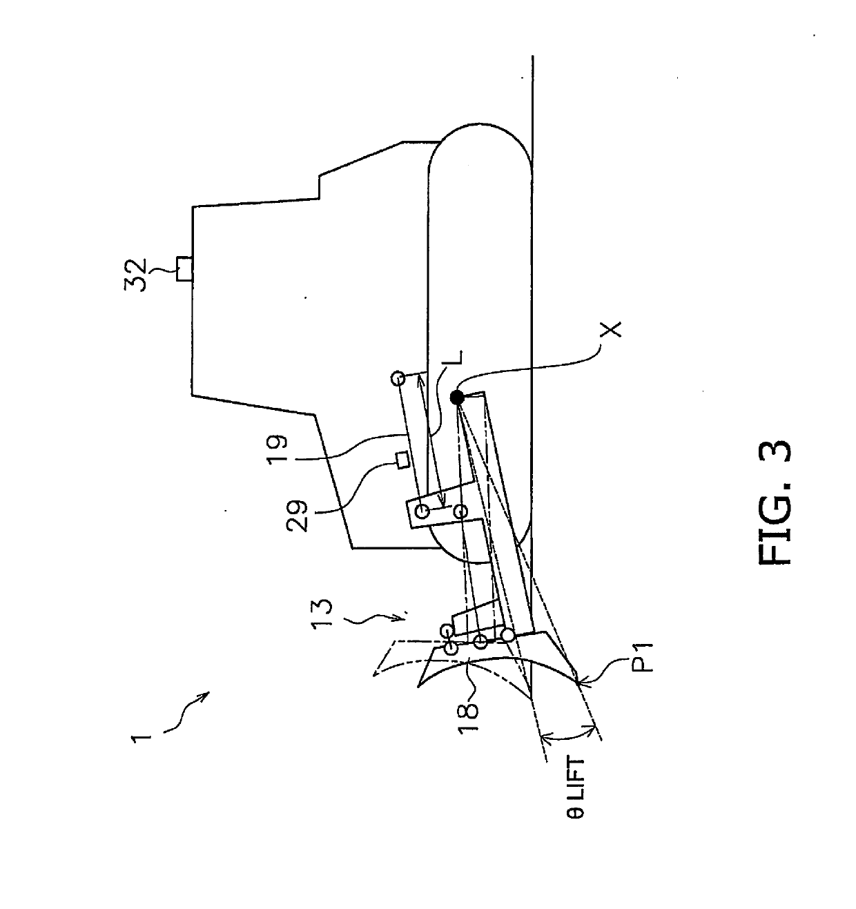
[0035]The work implement 13 is attached to the vehicle body 11. The work implement 13 has a lift frame 17, a blade 18, a lift cylinder 19...


PUM


Abstract

A work vehicle control system includes an actual topography acquisition device, a storage device, and a controller. The actual topography acquisition device acquires actual topography information, which indicates the actual topography of a work target. The storage device stores design topography information, which indicates a final design topography that is a target topography of the work target. The controller acquires the actual topography information from the actual topography acquisition device. The controller acquires the design topography information from the storage device. The controller generates a command signal to move the work implement to a position that is between the actual topography and the final design topography, and a predetermined distance above the actual topography.

Description

CROSS-REFERENCE TO RELATED APPLICATIONS[0001]This application is a U.S. National stage application of International Application No. PCT / JP2017 / 026913, filed on Jul. 25, 2017. This U.S. National stage application claims priority under 35 U.S.C. § 119(a) to Japanese Patent Application No. 2016-146381, filed in Japan on Jul. 26, 2016, the entire contents of which are hereby incorporated herein by reference.BACKGROUNDField of the Invention[0002]The present invention relates to a control system for a work vehicle, a control method, and a work vehicle.Background Information[0003]An automatic control for automatically adjusting the position of a work implement has been conventionally proposed for work vehicles such as bulldozers or graders and the like. For example, Japanese Patent Publication No. 5247939 discloses excavation control and leveling control.[0004]Under the excavation control, the position of the blade is automatically adjusted such that the load applied to the blade coincides...

Claims


Application Information

Patent Timeline
Patent Type & Authority Applications(United States)
IPC IPC(8): E02F9/20G06T7/529
CPCE02F9/2029E02F9/2033G06T7/529G06T2207/30181E02F3/7609E02F9/261E02F9/264E02F9/2045E02F9/20
Inventor ISHIBASHI, EIJIINAMARU, AKIFUMIYONEZAWA, YASUHITOSHIMOJO, TAKAHIRO
Owner KOMATSU LTD
Why Eureka
Try Eureka