Single valve for gas grill with multiple burners

a single valve and gas grill technology, applied in the field of gas grills, can solve the problems of overly complicated adjustment of all individual burners to different settings, and the mess of charcoal of grillers

Inactive Publication Date: 2019-03-28
WEBER-STEPHEN PRODUCTS
View PDF8 Cites 4 Cited by
  • Summary
  • Abstract
  • Description
  • Claims
  • Application Information

AI Technical Summary

Benefits of technology

[0012]The preferred gas control valve of the present invention includes a valve stem operably coupled to a control cone having a plurality of apertures, such that the amount of gas delivered to a particular burner tube is adjusted by turning th

Problems solved by technology

For example, some grillers don't like the mess of charcoal and particularly, lighting or starting the charcoal.
Some

Method used


Image

  • Single valve for gas grill with multiple burners
  • Single valve for gas grill with multiple burners
  • Single valve for gas grill with multiple burners

Examples


Embodiment Construction

[0019]Set forth below is a description of what is currently believed to be the preferred embodiments or best representative examples of the inventions claimed. Future and present alternatives and modifications to the embodiments and preferred embodiments are contemplated. Any alternatives or modifications which make insubstantial changes in function, purpose, structure or result are intended to be covered by the claims of this patent.

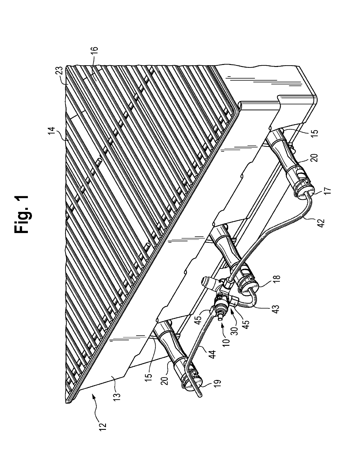
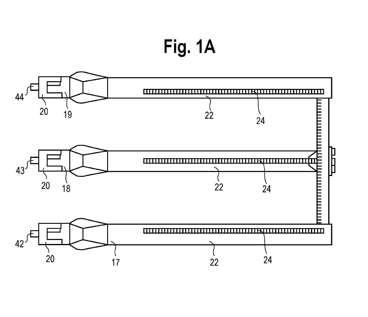
[0020]The one valve, multiple burner gas delivery system of the present inventions is shown as 10 in FIG. 1 and is incorporated into a typical, three burner gas grill. A typical firebox 12 having a front portion 13 and a rear portion 23 of a typical gas grill is also shown. The firebox 12 typically supports a cooking grate 14 and other heat deflecting devices 16. Extending into the firebox 12 is a plurality of burner tubes 17, 18 and 19, also referred to herein as burners.

[0021]Burner tubes 17, 18 and 19 extend into firebox 12, typically through holes 1...


PUM


Abstract

A gas delivery system for gas grills is provided, the delivery system including one gas valve that controls the gas flow to a plurality of burner tubes.

Description

FIELD OF THE INVENTION[0001]The present inventions relate to gas grills. In particular, the present inventions relate to gas grills having a gas delivery system with one valve that controls multiple burners to easily enable a wide range of cooking conditions.BACKGROUND OF THE INVENTION[0002]Grilling is exceedingly popular. The use of gas grills is also extremely popular for a variety of reasons. For example, some grillers don't like the mess of charcoal and particularly, lighting or starting the charcoal. Some grillers also like the control and relative ease of use of gas grills.[0003]Typical gas grills include a cooking chamber or firebox to which a lid is hinged. The firebox is usually supported on a cart or stand for ease of use. The firebox houses a plurality of burner tubes or burners that provide gas to be ignited inside of the firebox. Most gas grills have at least two, and up to six or more, burners. Cooking grates and other heat distribution members are also provided, most ...

Claims


Application Information

Patent Timeline
IPC IPC(8): F23N1/00A47J37/07
CPCF23N1/007A47J37/0713F23N2023/50F23N2035/16F23N2039/04F23N2041/08A47J37/06F23D14/46A47J37/0727A47J37/0786F23N2223/50F23N2235/16F23N2239/04F23N2241/08
Inventor KALISIAK, ANTON
Owner WEBER-STEPHEN PRODUCTS
Why Eureka
Try Eureka