Flexible substrate

a flexible substrate and substrate technology, applied in the field of display, can solve the problems of reducing the precision of positioning, unsatisfactory display effect, performance of a flexible display device, etc., and achieve the effect of avoiding the impact of film thickness increase, reducing phase display, and improving display

Active Publication Date: 2019-03-28
SHENZHEN CHINA STAR OPTOELECTRONICS TECH CO LTD
View PDF3 Cites 1 Cited by
  • Summary
  • Abstract
  • Description
  • Claims
  • Application Information

AI Technical Summary

Benefits of technology

[0023]With respect to the flexible substrate provided according to the present disclosure, the second film is arranged to counteract the birefringence effect generated by the first film so as to eliminate the phase display and improve the display effect. Besides, impacts on the substrate due to increasing of the film thickness can be avoided, and the thickness of the flexible substrate can be determined according to actual needs. Since the flexible display panel comprises the flexible substrate provided in the present disclosure, the display effect thereof can be improved greatly. In addition, an ultrathin design of the flexible display panel can be realized.

Problems solved by technology

Liquid crystal display device and organic light emitting diode display device, as two important development fields of the flexible display device, face same problems during development process, i.e., a selection of materials of a flexible substrate and manufacturing thereof.
High temperature in the manufacturing procedure may cause hot deformation of a substrate, which reduces precision of positioning.
Moreover, an excessive variation of a dimension of the substrate may cause unsatisfactory display effect due to an internal stress between surfaces of materials and a separation between layers when the substrate is bent.
When exposed in an environment of water vapor and oxygen, performance of a display medium of the flexible display device, organic materials in the organic light emitting diode in particular, may degrade rapidly.
However, a traditional polyimide film has great phase retardation.
For the display device, the phase retardation (or birefringence) of a flexible substrate in the thickness direction may easily cause light leakage from a side view direction, which affects the display effect.

Method used


Image

  • Flexible substrate
  • Flexible substrate
  • Flexible substrate

Examples


embodiment 1

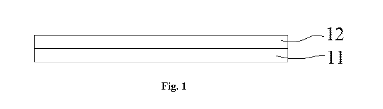
[0033]FIG. 1 schematically shows a structure of a flexible substrate according to the present embodiment. It can be seen from FIG. 1 that, the flexible substrate comprises a first film 11 and a second film 12 arranged from bottom to top in sequence. The second film 12 is arranged to counteract birefringence effect generated by the first film 11 so as to eliminate phase retardation. When light runs through the first film 11 along a normal line direction, the birefringence effect is generated along a thickness direction of the first film 11, and thus the phase retardation occurs. Moreover, with increasing of thickness of the first film 11, the phase retardation increases, which affects display effect. After the birefringence effect generated by the first film 11 is counteracted by the second film 12, the phase retardation can be eliminated and the display effect can be improved. Besides, impacts on the substrate due to increasing of film thickness can be avoided.

[0034]Preferably, the ...

embodiment 2

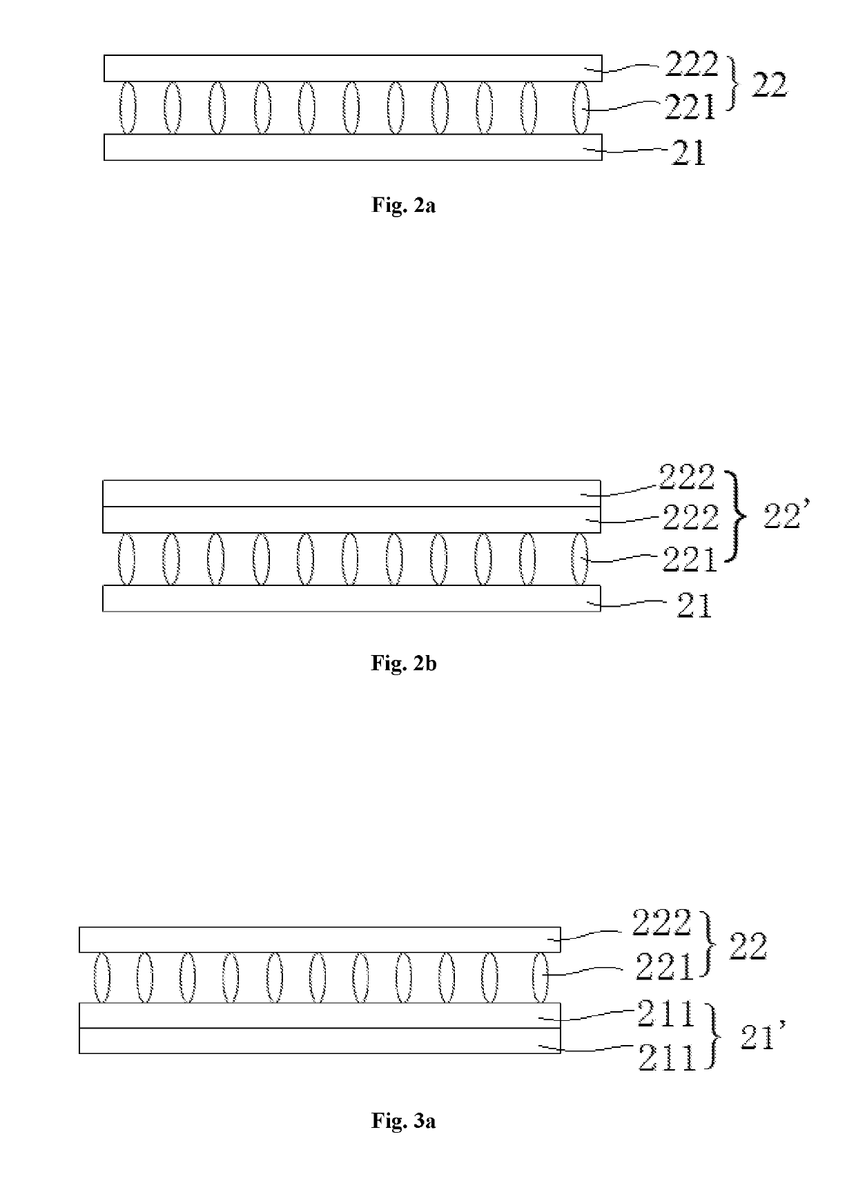
[0035]FIG. 2a schematically shows a structure of a flexible substrate according to the present embodiment. It can be seen from FIG. 2a that, the flexible substrate comprises a first film 21 and a second film 22 arranged from bottom to top in sequence. The second film 22 is arranged to counteract birefringence effect generated by the first film 21 so as to eliminate phase retardation. When light runs through the first film 21 along a normal line direction, the birefringence effect is generated along a thickness direction of the first film 21, and thus the phase retardation occurs. Moreover, with increasing of thickness of the first film 21, display effect is affected. After the birefringence effect generated by the first film 21 is counteracted by the second film 22, the phase retardation can be eliminated and the display effect can be improved. Besides, impacts on the substrate due to increasing of film thickness can be avoided.

[0036]It can be seen from FIG. 2a that, the second film...

embodiment 3

[0038]FIG. 3a schematically shows a structure of a flexible substrate according to the present embodiment. The present embodiment differs from embodiment 2 in that, the first film 21 comprises at least one base film 211. Preferably, the base film 211 is a negative polyimide film with an optical axis perpendicular to a surface thereof.

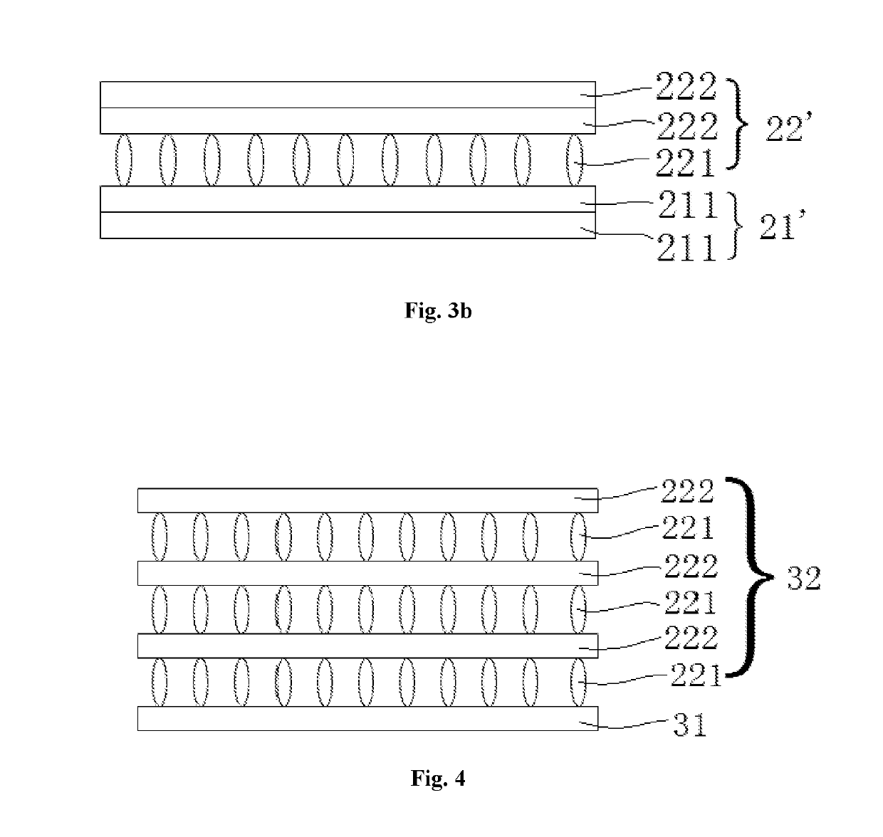
[0039]The flexible substrate in the present embodiment can achieve a same technical effect as that of the flexible substrate in embodiment 2. According to the present embodiment, the number of the base film 211 and the number of the protection film 222 can both be arranged so as to change the thickness of the flexible substrate. FIG. 3b schematically shows a structure of a flexible substrate which comprises two base films 211 and two protection films 222 according to the present embodiment.


PUM

PropertyMeasurementUnit
flexibleaaaaaaaaaa
Flexibleaaaaaaaaaa
heat resistanceaaaaaaaaaa

Abstract

Disclosed is a flexible substrate, which relates to the technical field of display. The flexible substrate includes a first film and a second film arranged from bottom to top in sequence. The second film is arranged to counteract birefringence effect generated by the first film so as to eliminate phase retardation of the flexible substrate. Thus, display effect can be improved, and impacts on a substrate due to increasing of film thickness can also be avoided. Besides, thickness of the flexible substrate can be determined according to actual needs.

Description

CROSS-REFERENCE TO RELATED APPLICATIONS[0001]This application claims the priority of Chinese patent application CN201710227479.6, entitled “Flexible substrate” and filed on Apr. 10, 2017, the entirety of which is incorporated herein by reference.FIELD OF THE INVENTION[0002]The present disclosure relates to the technical field of display, and in particular, to a flexible substrate.BACKGROUND OF THE INVENTION[0003]As a main carrier and a material basis for information exchange and transmission, display devices, such as liquid crystal display (LCD) device and organic light emitting diode (OLED) display device, draw attention of more and more people, and are widely used in various aspects of work and life. In recent years, flexible display becomes popular among consumers in the industry, and in particular, industries of flexible thin film transistor liquid crystal display (TFT-LCD) and flexible organic light emitting diode (OLED) have gradually become most promising high-tech industries...

Claims


Application Information

Patent Timeline
Patent Type & Authority Applications(United States)
IPC IPC(8): G02F1/1333G02F1/13363
CPCG02F1/133305G02F1/13363G02B5/3083B32B27/08B32B27/281B32B2307/42Y02E10/549C09K2323/06C09K2323/03G02F1/133635G02F1/133634H10K77/111H10K50/85H10K2102/311B29D11/00788B29D11/0073
Inventor LI, MINGHUI
Owner SHENZHEN CHINA STAR OPTOELECTRONICS TECH CO LTD
Why Eureka
Try Eureka