Ohmmeter for sensor electrodes

Active Publication Date: 2019-03-28
SYNAPTICS INC
View PDF3 Cites 7 Cited by
  • Summary
  • Abstract
  • Description
  • Claims
  • Application Information

AI Technical Summary

Benefits of technology

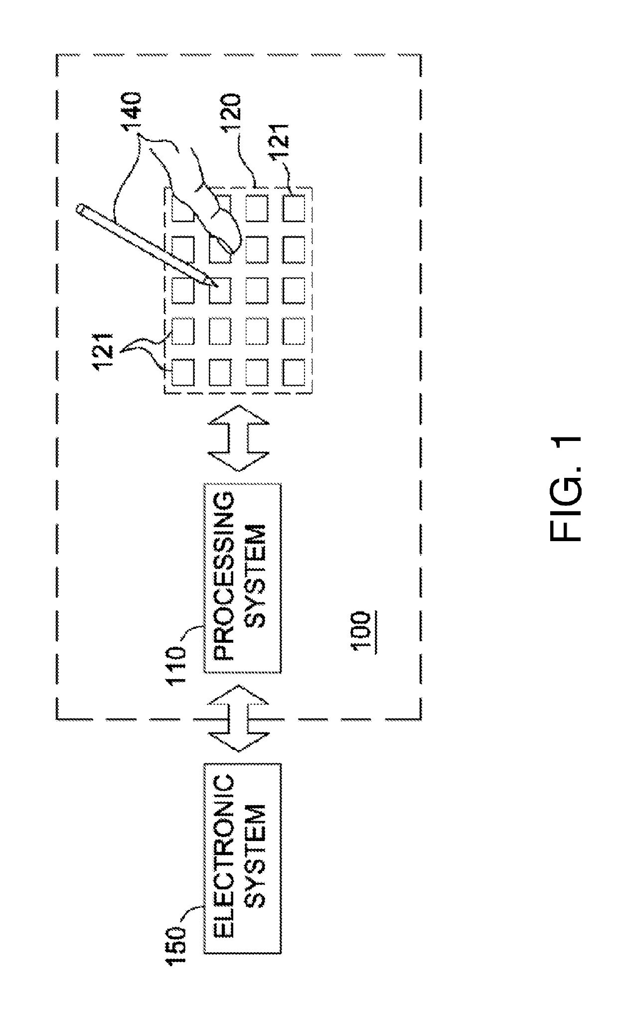
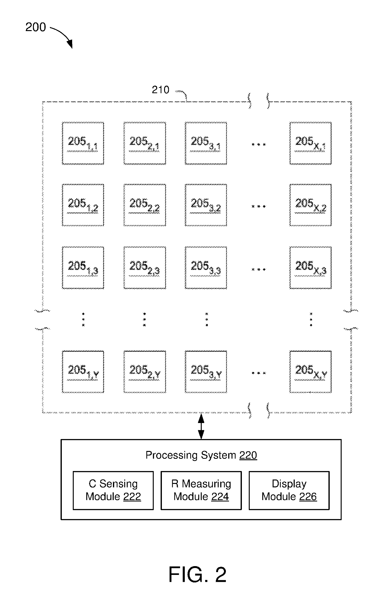
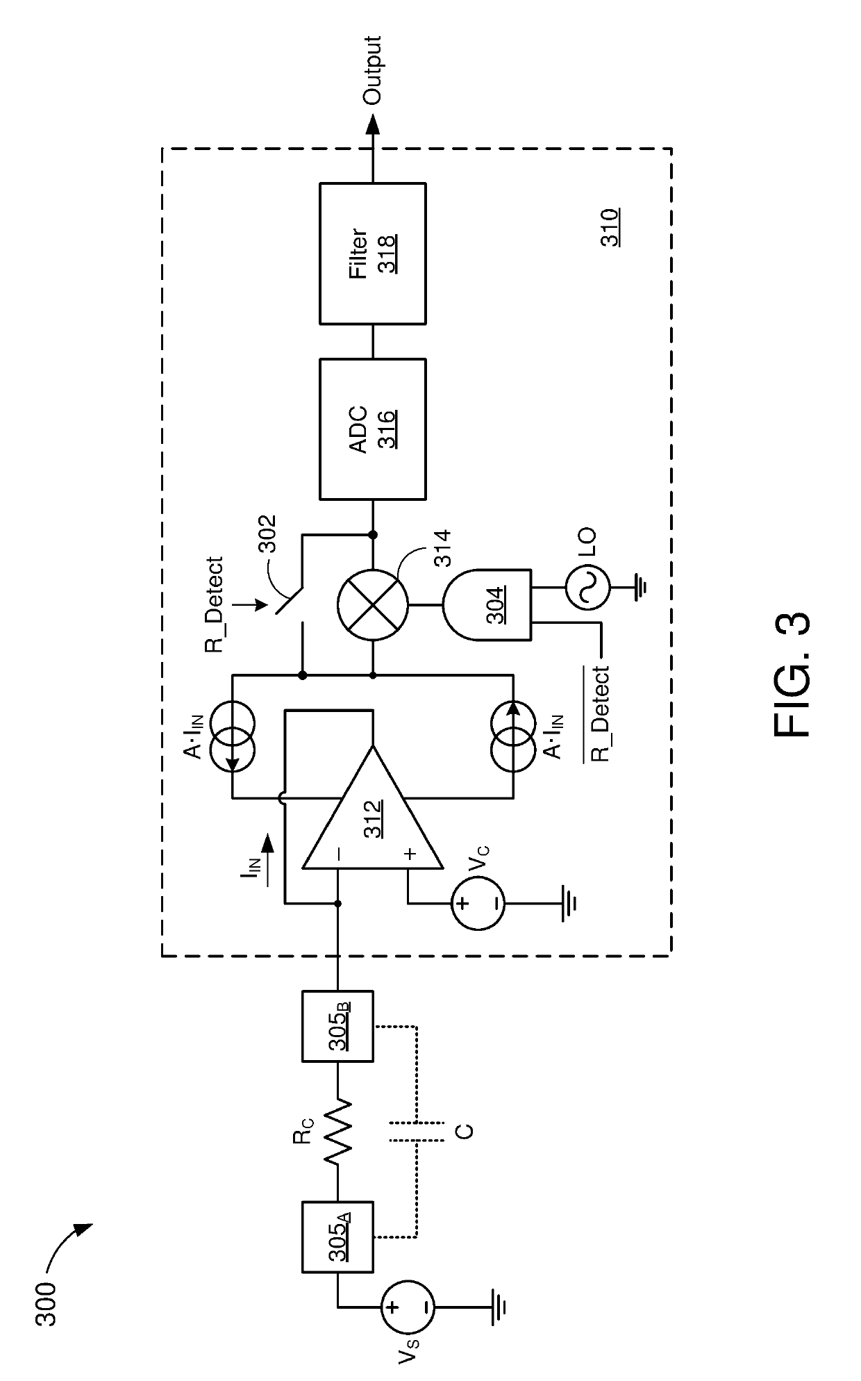
The patent describes a method to measure the resistance between sensor electrodes of an input device. This can be used to detect user inputs or detect electrical shorts between the electrodes. The method involves measuring current and capacitance or resistance in two different modes. The processing system can use time-varying voltage or constant voltage to produce the current. An amplifier, analog-to-digital converter, and mixer can be used in the processing system. The technical effect of this patent is to provide a more precise and reliable way to measure resistance between sensor electrodes in an input device.

Problems solved by technology

However, manufacturing defects may cause two or more of the conductors to become shorted together.
As a result, such conductors may be ineffective and / or inoperable as proximity sensors.

Method used


Image

  • Ohmmeter for sensor electrodes
  • Ohmmeter for sensor electrodes
  • Ohmmeter for sensor electrodes

Examples


Embodiment Construction

[0018]In the following description, numerous specific details are set forth such as examples of specific components, circuits, and processes to provide a thorough understanding of the present disclosure. The term “coupled” as used herein means connected directly to or connected through one or more intervening components or circuits. Also, in the following description and for purposes of explanation, specific nomenclature is set forth to provide a thorough understanding of the aspects of the disclosure. However, it will be apparent to one skilled in the art that these specific details may not be required to practice the example embodiments. In other instances, well-known circuits and devices are shown in block diagram form to avoid obscuring the present disclosure. Some portions of the detailed descriptions which follow are presented in terms of procedures, logic blocks, processing and other symbolic representations of operations on data bits within a computer memory. The interconnec...


PUM


Abstract

An input device includes a plurality of sensor electrodes and a processing system that is operable in at least a first mode or a second mode. The processing system is configured to receive an input current from a pair of the sensor electrodes. When operating the first mode, the processing system is configured to measure a capacitance across the pair of sensor electrodes based on the received input current. When operating the second mode, the processing system is configured to measure a resistance between the pair of sensor electrodes based on the received input current.

Description

CROSS-REFERENCE TO RELATED APPLICATION[0001]This application claims priority and benefit under 35 USC § 119(e) to U.S. Provisional Patent Application No. 62 / 561,945, filed on Sep. 22, 2017, which is incorporated herein by reference in its entirety.TECHNICAL FIELD[0002]The present embodiments relate generally to capacitive sensing, and specifically to measuring a resistance between sensor electrodes.BACKGROUND OF RELATED ART[0003]Input devices including proximity sensor devices are widely used in a variety of electronic systems. A proximity sensor device may include a sensing region, often demarked by an input surface, in which the proximity sensor device determines the presence, location, force, and / or motion of one or more input objects. Proximity sensor devices may be used to provide interfaces for the electronic system. For example, proximity sensor devices may be used as input devices for larger computing systems (such as opaque touchpads integrated in, or peripheral to, noteboo...

Claims


Application Information

Patent Timeline
IPC IPC(8): G06F3/044H03K17/96G06F3/041
CPCH03K17/962G06F3/044G06F3/0416G06F2203/04112H03K17/9645G06F3/0412G06F3/0418G06F2203/04105G06F2203/04106G06F3/04166G06F3/0414
Inventor BOHANNON, ERIC SCOTTLO, STEVE CHIKINSHEPELEV, PETR
Owner SYNAPTICS INC
Why Eureka
Try Eureka