Supercharge Your Innovation With Domain-Expert AI Agents!

Overmolded lead frame providing contact support and impedance matching properties

a lead frame and contact support technology, applied in the direction of coupling device connection, securing/insulating coupling contact member, electrical apparatus, etc., can solve the problem that the integrity of electrical signals may be affected, and achieve the effect of improving impedance matching

Active Publication Date: 2019-03-28
SAMTEC
View PDF1 Cites 21 Cited by
  • Summary
  • Abstract
  • Description
  • Claims
  • Application Information

AI Technical Summary

Benefits of technology

The present invention provides a connector that solves issues in high-speed applications by improving impedance matching. This connector has a material between the contacts that deflects with the contacts.

Problems solved by technology

As electrical signals are transmitted between the pads of the edgecard and the traces in the PCB, the electrical signals may experience degradation in signal integrity due to the changing transmission line impedance along the signal path.

Method used


Image

  • Overmolded lead frame providing contact support and impedance matching properties
  • Overmolded lead frame providing contact support and impedance matching properties
  • Overmolded lead frame providing contact support and impedance matching properties

Examples


Embodiment Construction

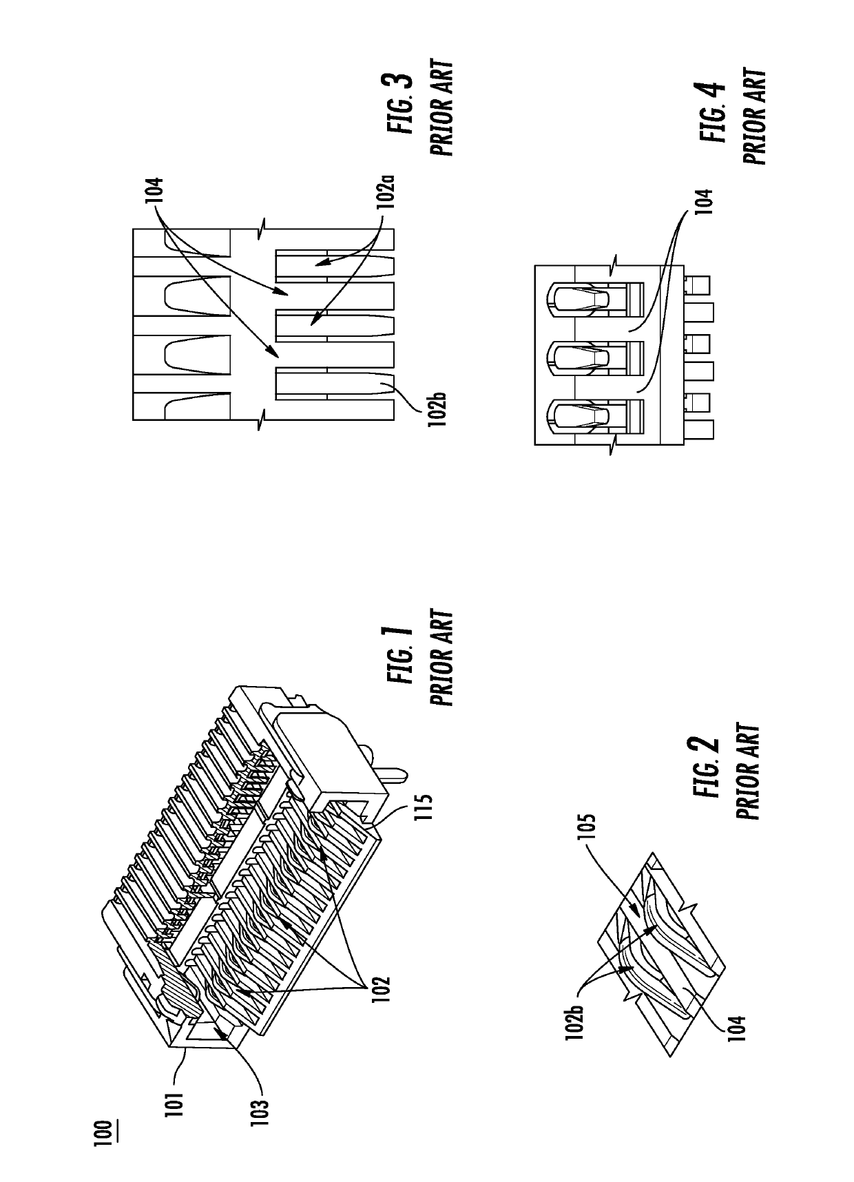
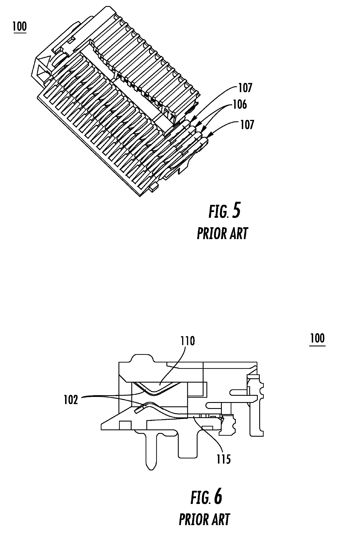
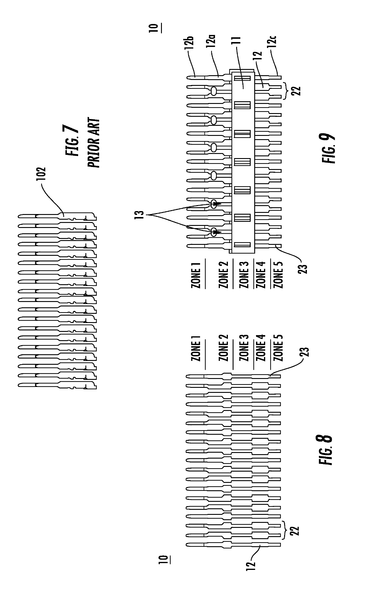
[0056]FIGS. 8-23 show lead frames according to preferred embodiments of the present invention. The lead frames shown in FIGS. 8-18 can be used as a bottom row of contacts, and the lead frames shown in FIG. 19-23 can be used as a top row of contacts. The lead frames can be used in any suitable connector, including a connector similar to the one shown in FIGS. 1 and 5. The lead frames can be used in connectors with housings that do not include walls or ribs between adjacent contacts. The lead frames can also be used in the connector shown in FIGS. 24 and 25 that have ribs between the ground contacts and the pairs of differential signal contacts, but not between the pairs of differential signal contacts. It is possible to use the lead frames shown in FIGS. 8-23 in a connector with only a single row of contacts. It is also possible to use more than one lead frame per row of contacts. It is possible to use the techniques discussed below to tune the impedance of the differential pairs to ...


PUM


Abstract

An electrical connector includes first and second adjacent electrical contacts that each define respective first and second mating ends, the first mating end of a first one of the first and second adjacent electrical contacts defines a first contact surface, the second mating end of a second one of the first and second adjacent electrical contacts defines a second contact surface electrically isolated from the first contact surface; and a dielectric material positioned between the first and second adjacent electrical contacts. When a mating connector applies a force to the first contact surface and the second contact surface, the first and second mating ends and the dielectric material all move in a first direction.

Description

BACKGROUND OF THE INVENTION1. Field of the Invention[0001]The present invention relates to connectors. More specifically, the present invention relates to a connector with an overmolded lead frame that includes a web between adjacent contacts.2. Description of the Related Art[0002]A known connector 100 is shown in FIG. 1. The connector 100 includes a housing 101 that surrounds contacts 102 that transmit electrical signals. A portion of the housing 101 in FIG. 1 is cut away to show the bottom row 115 of contacts 102. Although not shown in FIG. 1, the connector 100 is typically mounted to a printed circuit board (PCB). The PCB includes traces that transmit electrical signals. The housing 101 includes an opening 103 into which, for example, an edgecard can be inserted. The edgecard includes pads that engage with the beams 102a of the contacts 102. The beams 102a deflect as the edgecard is inserted into the housing 101, creating a mechanical and electrical connection between the contact...

Claims


Application Information

Patent Timeline
Patent Type & Authority Applications(United States)
IPC IPC(8): H01R13/6477H03H7/38H01R12/72H01R13/41
CPCH01R13/6477H03H7/38H01R12/724H01R13/41H01R13/646H01R13/514H01R13/6315H01R13/2442H01R13/6471H01R12/721
Inventor MONGOLD, JOHN A.BUCK, JONATHAN E.
Owner SAMTEC
Features
  • R&D
  • Intellectual Property
  • Life Sciences
  • Materials
  • Tech Scout
  • Unparalleled Data Quality
  • Higher Quality Content
  • 60% Fewer Hallucinations
Learn More