Eureka AIR delivers breakthrough ideas for toughest innovation challenges, trusted by R&D personnel around the world.

Apparatus for moving articles

Active Publication Date: 2019-04-04
IMMOBILIARE METALPROGETTI
View PDF10 Cites 1 Cited by
  • Summary
  • Abstract
  • Description
  • Claims
  • Application Information

AI Technical Summary

Benefits of technology

The technology described in this patent allows for a safer movement apparatus by positioning the mobile parts of the drive unit in a protected position with respect to the aperture defined by the guide cavity. This eliminates the possibility of accidents, such as pinching or severing of fingers, should anyone put their fingers in the aperture. The guide cavity and the positioning of the drawing zone of the conveyor member create a safety protection without using dedicated protection bodies. The drive wheel can be rubberized to eliminate noise from moving mechanical parts. The drive wheel has a plurality of drawing teeth that cooperate with the drawing zone to move the conveyor member ensuring sure movement without sliding.

Problems solved by technology

The size of the aperture therefore does not prevent or exclude a user from accidentally inserting his / her fingers therein, even only partly, and thus being hurt quite seriously by the action of the drive wheel on the drive unit.
This solution is particularly dangerous since it disposes the moving parts of the drive unit in a position directly accessible for the operator, but also other persons, for example children who voluntarily or not can easily come into contact with the moving parts.
Another problem of this known solution is that, when an article has protruding and / or voluminous parts, these can come into contact with the drive unit, damaging the article and blocking the movement of the conveyor member.
However, this configuration is subject to frequent blockages.
Furthermore, this solution too provides that the drive unit is positioned in direct proximity to the aperture of the guide cavity, causing problems of potential danger for users, and problems of blockages.

Method used


Image

  • Apparatus for moving articles
  • Apparatus for moving articles
  • Apparatus for moving articles

Examples


Embodiment Construction

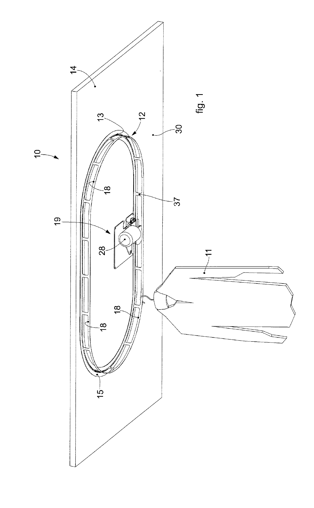
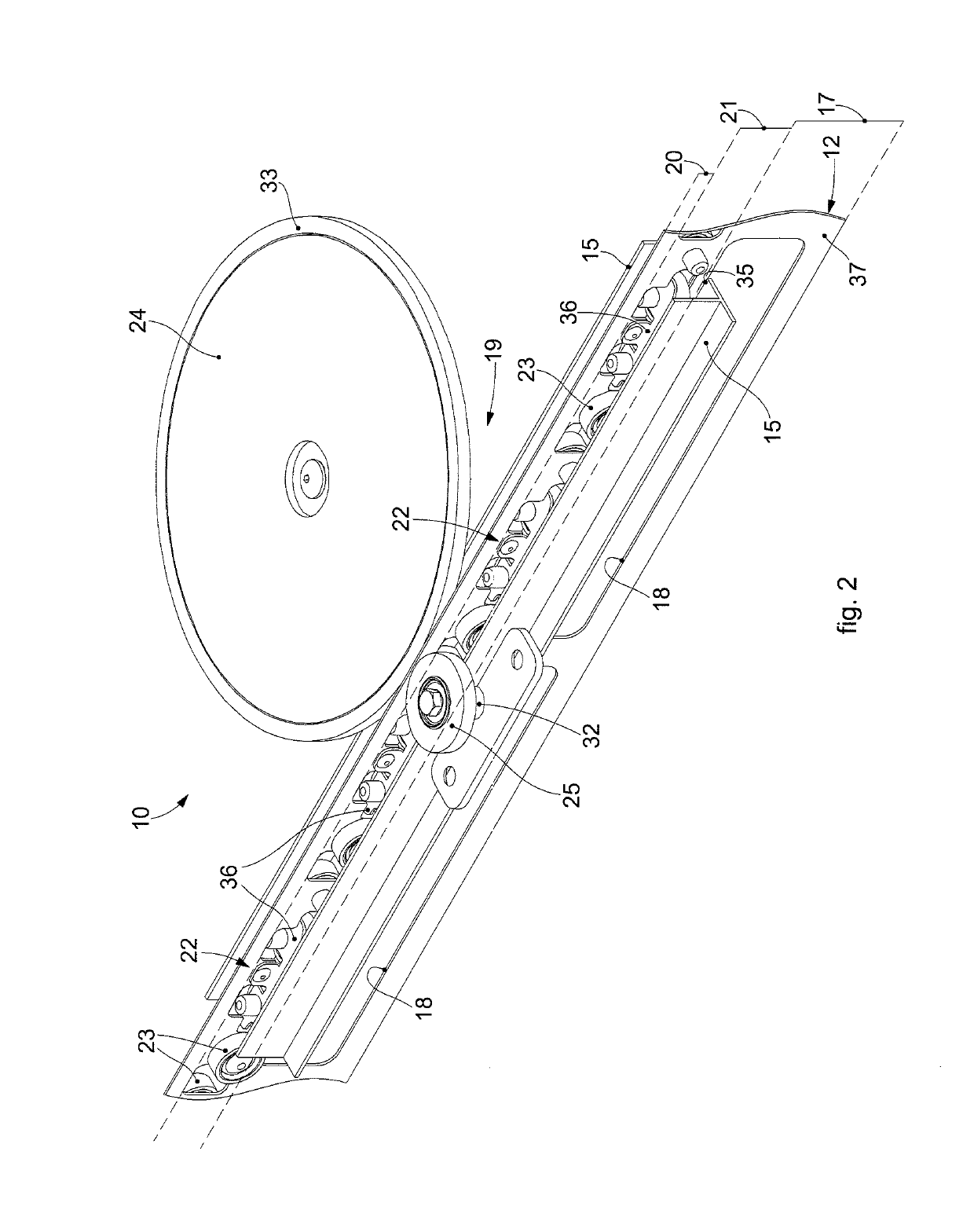
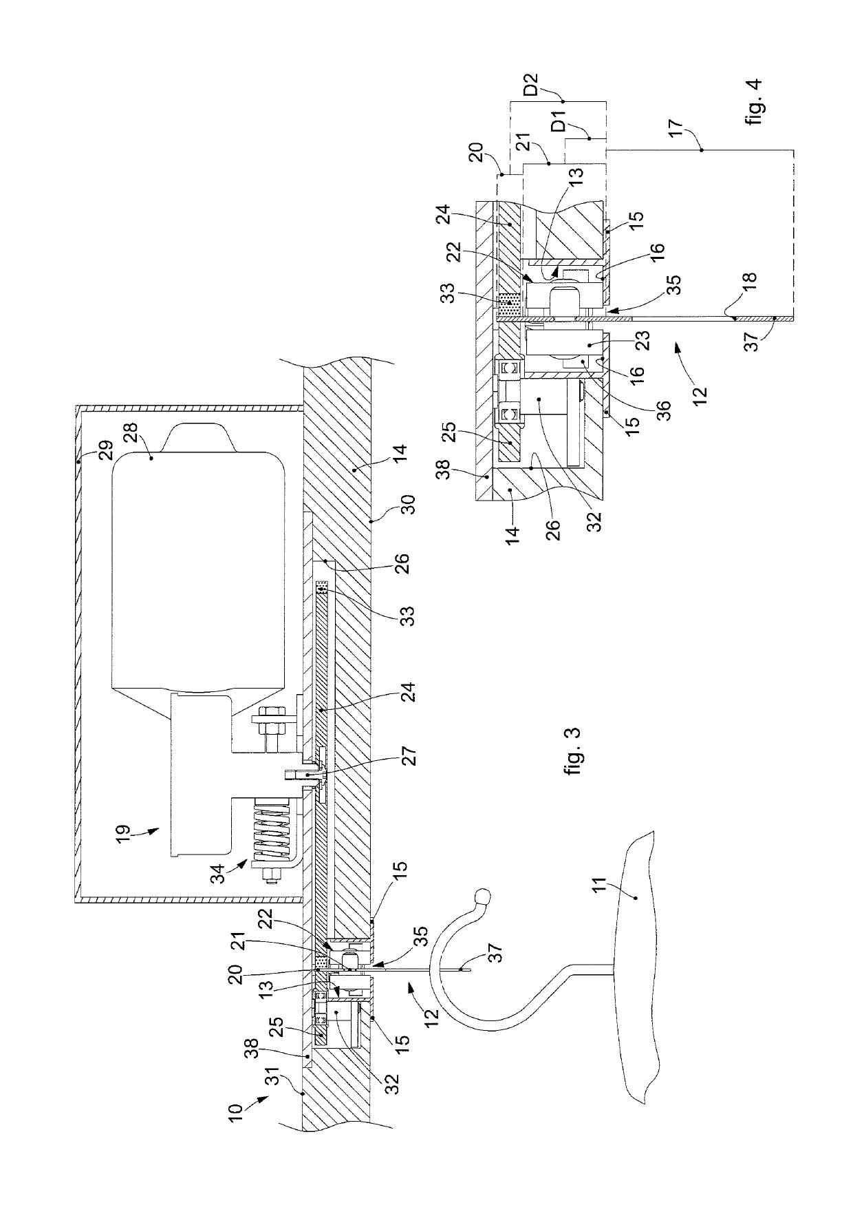
[0043]With reference to the attached drawings, which show non-restrictive examples of the invention, we will now describe some embodiments of an apparatus 10 for moving articles 11.

[0044]According to one aspect of the present invention, the movement apparatus 10 comprises a conveyor member 12 with an oblong development, closed-ring or linear depending on the specific conveying requirements, with which at least one article 11 can be associated.

[0045]The movement apparatus 10 also comprises a shelf 14 with which the conveyor member 12 is associated. The shelf 14 can itself define a plane that can be attached for example to a wall or ceiling, or it can be part of a furnishing element such as a wardrobe, walk-in closet or suchlike.

[0046]The movement path of the conveyor member 12 is defined by a guide cavity 13 provided in the shelf 14 which is coherent with the development of the conveyor member 12, that is, it can be a closed or open path and conformed on each occasion in a desired ma...


PUM


Abstract

Apparatus for moving articles comprising a conveyor member, a shelf provided with a guide cavity defining at least partly a movement path and a drive unit associated with the conveyor member and configured to move the conveyor member along the movement path. The conveyor member is provided with a support zone, a drawing zone, and an intermediate zone.

Description

FIELD OF THE INVENTION[0001]The present invention concerns an apparatus for moving articles that can be installed for example in furnishing elements used as wardrobes.[0002]In particular, the present invention can be used, merely by way of example, in the home, in hotels, or in commercial activities selling clothes, for the temporary or intennediate storage of articles or garments.BACKGROUND OF THE INVENTION[0003]Different types of movement apparatuses are known, used for temporarily storing and moving articles in order to make them selectively removable by an operator or other person from a desired position.[0004]A movement apparatus is known, for example from document WO-A-2015 / 008173, integrated in a shelf possibly of a furnishing element, which comprises a conveyor member.[0005]By way of non-restrictive example, by shelf we mean an element of a wardrobe or other furnishing element or it can be an element that can be inserted in a wall or the actual wall itself.[0006]The conveyor...

Claims


Application Information

Patent Timeline
IPC IPC(8): A47F5/025B65G17/20A47B61/00A47F7/24
CPCA47F5/025B65G17/20A47B61/00A47F7/24B65G2201/0229
Inventor SANTICCHI, AUGUSTO
Owner IMMOBILIARE METALPROGETTI
Why Eureka
Eureka Blog
Learn More