
Liquid cooling device

Inactive Publication Date: 2019-04-04
AURAS TECH
View PDF13 Cites 0 Cited by
  • Summary
  • Abstract
  • Description
  • Claims
  • Application Information

AI Technical Summary

Benefits of technology

The present invention is a small-size liquid cooling device that is easier to produce and install compared to conventional technologies. It also minimizes the possibility of leaking the working medium. The device features a combined plate structure of an upper plate and a lower plate that integrates the functions of the liquid cooling head, radiator, and pump. This reduces the size of the device. It can be easily and quickly combined together using a laminating or welding process, simplifying the assembly process and minimizing the risk of leakage.

Problems solved by technology

However, as the trends of designing the electronic device is toward miniaturization, the structure of the liquid cooling device inside the electronic device is not applicable.

Method used


Image

  • Liquid cooling device
  • Liquid cooling device
  • Liquid cooling device

Examples


first embodiment

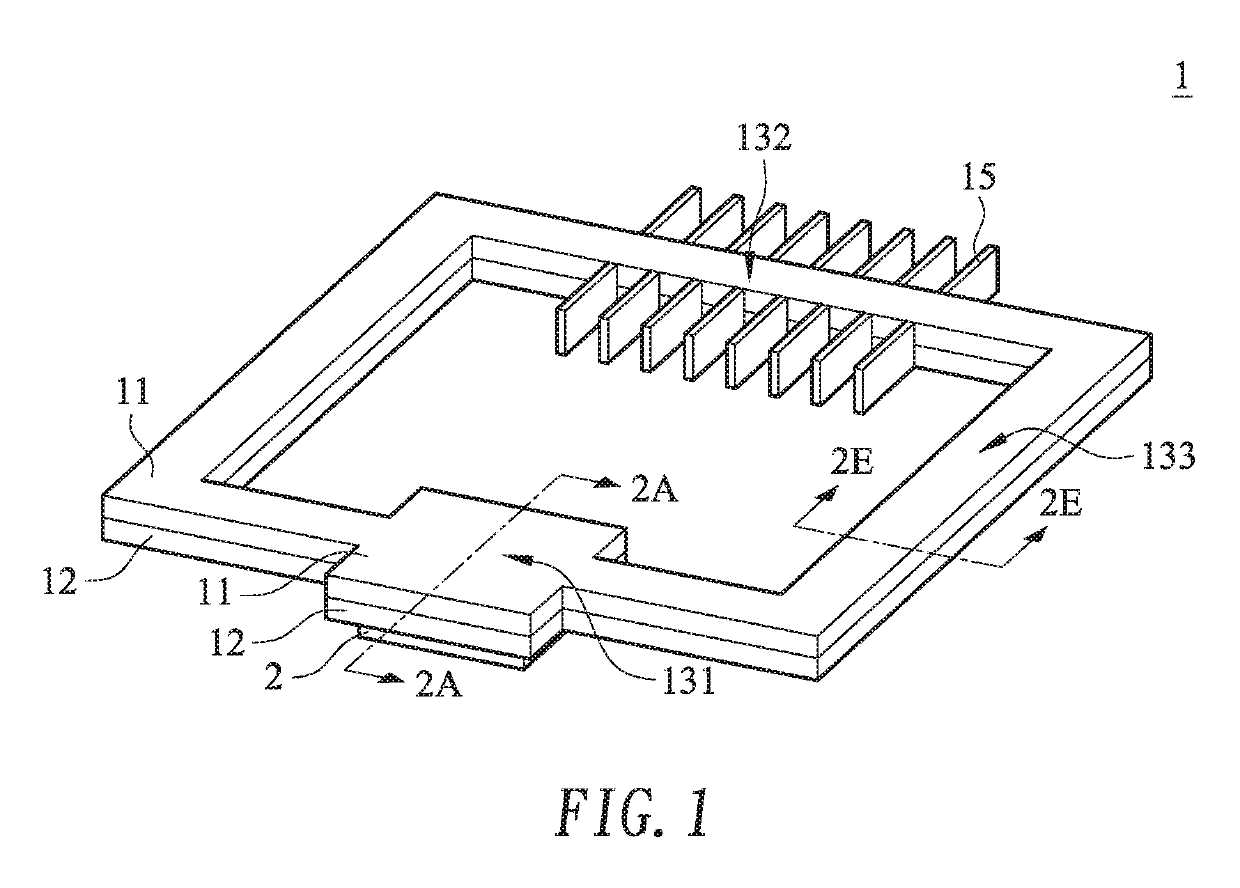
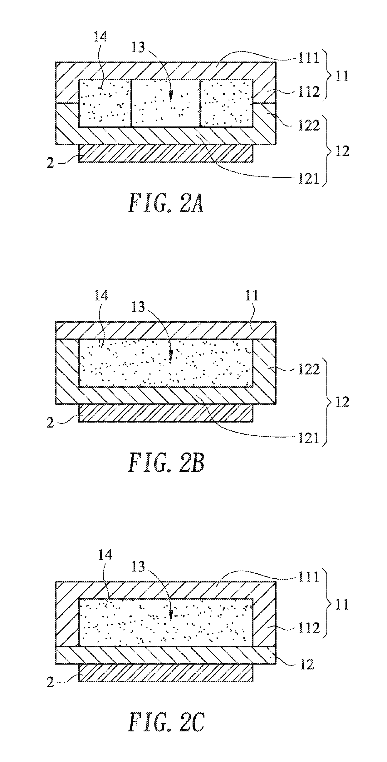
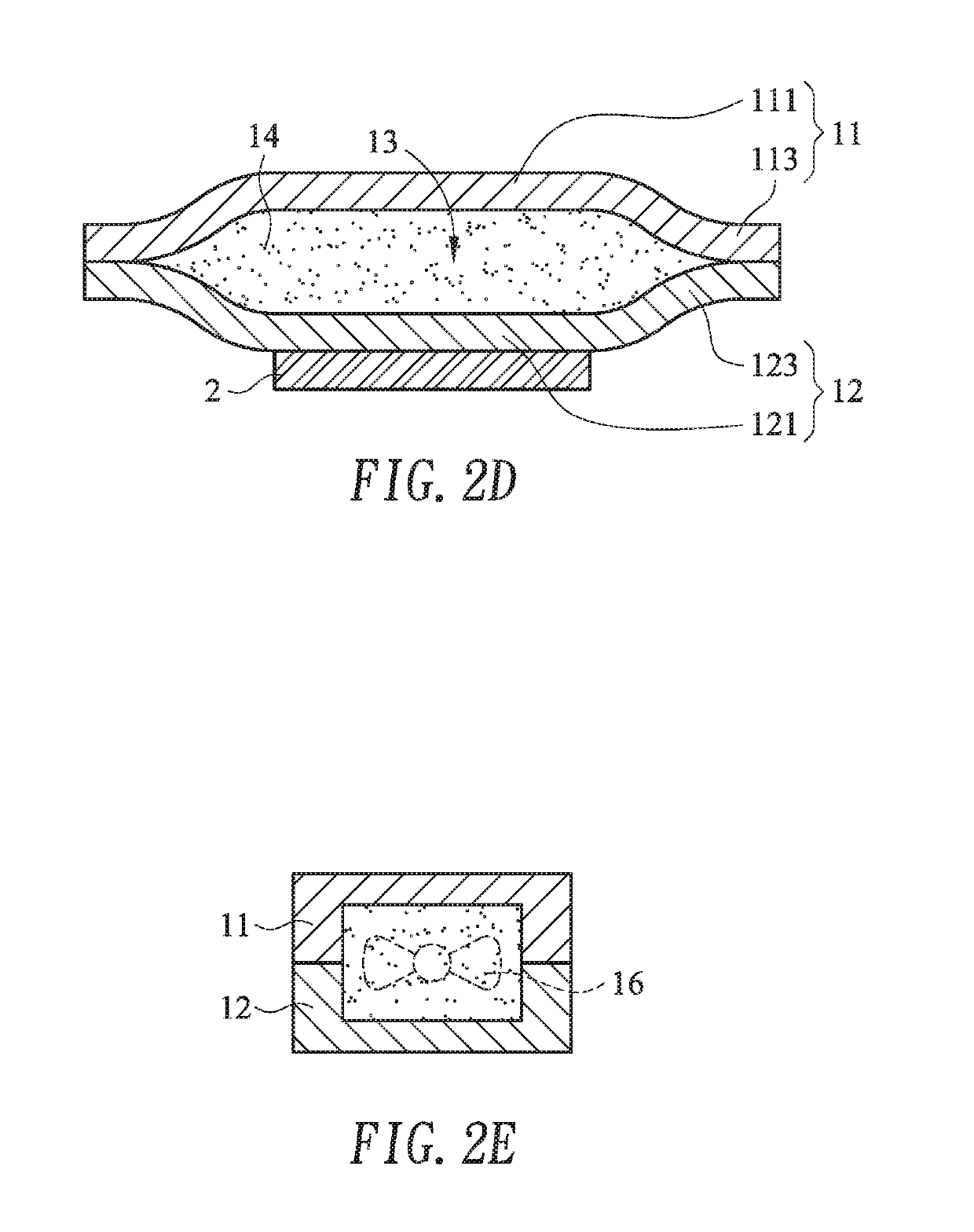
[0035]FIG. 1 is a schematic perspective view illustrating a liquid cooling device according to the present invention. FIG. 2A is a schematic cross-sectional view illustrating a heat-absorbing section of the liquid cooling device of FIG. 1 and taken along the line 2A-2A. As shown in FIGS. 1 and 2A, the liquid cooling device 1 comprises an upper plate 11 and a lower plate 12. The upper plate 11 and the lower plate 12 are combined together to define a chamber 13. A liquid working medium 14 is accommodated within the chamber 13. The chamber 13 comprises a heat-absorbing section 131, a heat-radiating section 132 and a driving section 133. The function of the heat-absorbing section 131 is similar to the function of a liquid cooling head. When the heat-absorbing section 131 is in thermal contact with a heat generation element 2, the heat from the heat generation element 2 is absorbed by the heat-absorbing section 131 and transferred to the liquid working medium 14. Consequently, the temper...

second embodiment

[0042]FIG. 3 is a schematic perspective view illustrating a liquid cooling device according to the present invention. FIG. 4A is a schematic cross-sectional view illustrating a heat-absorbing section of the liquid cooling device of FIG. 3 and taken along the line 4A-4A. FIG. 4B is a schematic cross-sectional view illustrating a first extension section of the liquid cooling device of FIG. 3 and taken along the line 4B-4B. FIG. 4C is a schematic cross-sectional view illustrating a second extension section of the liquid cooling device of FIG. 3 and taken along the line 4C-4C.

[0043]Please refer to FIGS. 3, 4A, 4B and 4C. In this embodiment, the liquid cooling device 3 comprises an upper plate 31, a lower plate 32, a liquid cooling radiator 35 and a driving device 36. The upper plate 31 and the lower plate 32 are combined together to define a chamber 33. A liquid working medium 34 is accommodated within the chamber 33. The chamber 33 comprises a heat-absorbing section 331, a first extens...


PUM


Abstract

A liquid cooling device includes an upper plate and a lower plate. The upper plate and the lower plate are combined together to define a chamber. A liquid working medium is accommodated within the chamber. The chamber includes a heat-absorbing section, a heat-radiating section and a driving section. The heat-absorbing section is in thermal contact with a heat generation element to absorb heat from a heat generation element. The heat is transferred to the liquid working medium, and a temperature of the liquid working medium is increased. The heat-radiating section is connected with a heat dissipation device. The heat is removed by the heat dissipation device, so that the temperature of the liquid working medium is decreased. The driving section is connected with a driving device. The liquid cooling medium with the decreased temperature is driven by the driving device and returned back to the heat-absorbing section.

Description

FIELD OF THE INVENTION[0001]The present invention relates to a cooling device, and more particularly to a slim-type liquid cooling device.BACKGROUND OF THE INVENTION[0002]Nowadays, a liquid cooling device is widely used. For example, a liquid cooling device disclosed in U.S. Pat. No. 6,725,682 comprises a liquid cooling head, a liquid cooling radiator and a liquid pump. The liquid cooling head, the liquid cooling radiator and the liquid pump are separate components. After the three components are connected with each other through communication pipes, a circular loop is defined. However, as the trends of designing the electronic device is toward miniaturization, the structure of the liquid cooling device inside the electronic device is not applicable. It is necessary to install the liquid cooling device in the narrow space while reducing the number of the communication pipes and avoiding liquid leakage.SUMMARY OF THE INVENTION[0003]For solving the drawbacks of the conventional techno...

Claims


Application Information

Patent Timeline
IPC IPC(8): F28F27/00F28D15/00
CPCF28F27/00F28D15/00F28D2021/0028F28F2265/16F28F2250/08F28D2021/0031F28F3/12F28D1/0308F28D2021/0029H01L23/427
Inventor WU, AN-CHIHCHEN, CHIH-WEI
Owner AURAS TECH
Learn More