
A crowd management system

a crowd management and system technology, applied in the field of crowd management system, can solve the problems of not being easily lured into moving into a different queue, occupying an unfamiliar area using the prescribed visual indication element, and ineffective in attracting a crowd to a shorter queue or a less crowded area

Active Publication Date: 2019-04-04
SIGNIFY HLDG BV
View PDF0 Cites 16 Cited by
  • Summary
  • Abstract
  • Description
  • Claims
  • Application Information

AI Technical Summary

Benefits of technology

The invention relates to a system for controlling the lighting in a certain area based on the number of people in that area. The system uses sensors to measure the presence of people and their movement. This information is used by a controller to adjust the lighting in the area to improve visibility and safety. The controller takes into account factors like the capacity of the area, the direction of movement of people, and the gazes of people. The system also ensures that the environmental effects of different areas are balanced to prevent discomfort or fatigue. The technical effect of the invention is to provide a dynamic and effective way to control lighting in an area based on the number and movement of people.

Problems solved by technology

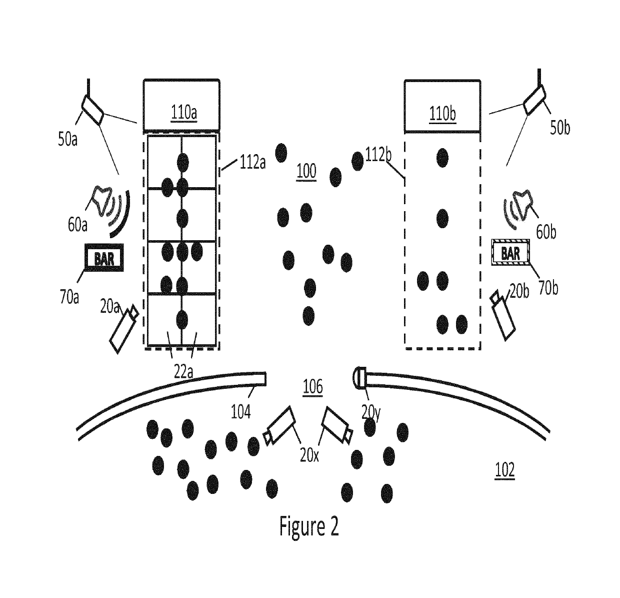
Given the overcrowded-ness and chaotic atmosphere in a stadium or a concert hall during an intermission, the area indication system as disclosed in WO2010 / 026521 may prove ineffective in attracting a crowd to a shorter queue or a less crowded area.
For example, assuming most of the visitors are occasional visitors and are unfamiliar with the venue, given the short window offered by the intermission, they may not be easily lured into moving into a different queue or to occupy an unfamiliar area using the prescribed visual indication element alone.

Method used


Image

  • A crowd management system
  • A crowd management system
  • A crowd management system

Examples


Embodiment Construction

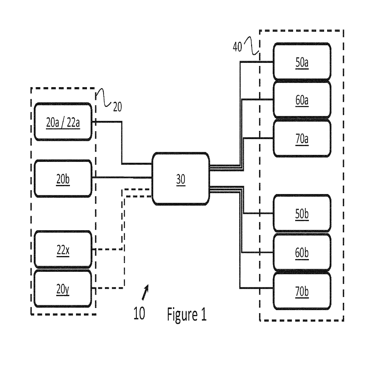
[0040]FIG. 1 illustrates an example of a crowd management system 10 according to the present invention. The crowd management system 10 comprises a controller 30 in communication with presence sensors 20 and environmental control elements 40. Said communication may be established by wired connections such as Ethernet, DMX, optical fibre and / or powerline connections, or the communication may be made using wireless communication technology including infrared or RF based technology such as Bluetooth, Wi-Fi or ZigBee. The wireless communication technology herein refers to a wireless communication protocol plus the necessary capability to transmit and / or receive on a suitable medium over a suitable frequency range and for the technology in question (e.g. a certain RF band or bands). Any of the communication may be established using one or more of the above-mentioned communications technologies and / or others.

[0041]The presence sensors 20 are deployed for capturing occupancy information of ...


PUM


Abstract

A crowd management system for influencing a crowd of people to distribute itself between a first region and a second region, comprising: at least one presence sensor configured to sense occupancy information from the first region and the second region; and a controller configured to receive said occupancy information from the at least one presence sensor; and at least one environmental control element configured to control an environmental effect in both the first region and second region; wherein said controller is configured to compare the occupancy information relating to the first region and the second region and based thereon to control the environmental effect in both the first region and the second region via the at least one environmental control element, such that the environmental effect in one of the first region or the second region is relatively more attractive or repellent than the other, in order to thereby influence at least a portion of the crowd to distribute or redistribute itself between the first region and the second region.

Description

TECHNICAL FIELD[0001]The present disclosure relates to a crowd management system. More specifically, the present disclosure relates to a crowd management system that influences a crowd of people to distribute itself amongst different regions by changing the crowd perception in said different regions.BACKGROUND[0002]Visitors attending large scale events at stadiums and concert halls are served by concession stands scattered all over these venues. The sales of food, beverages and merchandise at these concession stands presents a sizable source of income. However, the queuing time at these concession stands, as well as toilets and exits, varies significantly over the duration of the event. For example, the queues are often at their longest right before and after the event, as well as during the intermission.[0003]During these peak moments, an excessive visitor traffic leads to overcrowding as they move simultaneously from the seating area to concession stands in the atrium along relati...

Claims


Application Information

Patent Timeline
Patent Type & Authority Applications(United States)
IPC IPC(8): H05B37/02
CPCH05B37/0227H05B37/0236H05B47/115Y02B20/40H05B47/12
Inventor DEN HARTOG, EDITH DANIELLEHULTERMANS, MARTIJN MARIUS
Owner SIGNIFY HLDG BV
Learn More