Liquid crystal display device and method of controlling the same

a display device and liquid crystal technology, applied in static indicating devices, non-linear optics, instruments, etc., can solve the problems of liquid crystal deterioration and screen burn-in, and achieve the suppression of large bias, suppression of variable frame length, and suppression of burn-in.

Inactive Publication Date: 2019-04-11
SHARP KK
View PDF2 Cites 1 Cited by
  • Summary
  • Abstract
  • Description
  • Claims
  • Application Information

AI Technical Summary

Benefits of technology

[0036]According to the first aspect of the present invention, the polarity adjustment unit provided in the display control circuit adjusts the polarity of the liquid crystal application voltage such that the bias in the polarity of the liquid crystal application voltage is suppressed from increasing. Therefore, even when the frame frequency is changed in accordance with the change in the input frequency of the input image data, the occurrence of the bias in the polarity of the liquid crystal application voltage due to the variation in the length of the frame is suppressed. That is, even if the image display is performed while changing the frame frequency, the occurrence of the burn-in is suppressed. From the above, the occurrence of the burn-in caused by the bias in the polarity of the liquid crystal application voltage is suppressed in the liquid crystal display device configured to display the image while changing the frame frequency.
[0037]According to the second aspect of the present invention, the polarity signal is controlled by monitoring the polarity signal given to the liquid crystal panel drive circuit, and accordingly, a large bias is surely suppressed from occurring in the polarity of the liquid crystal application voltage.
[0038]According to the third aspect of the present invention, even if the polarity of the liquid crystal application voltage is biased, the voltage is applied to the liquid crystal so as to eliminate the bias.
[0039]According to the fourth aspect of the present invention, the same polarity voltage is prevented from being applied to the liquid crystal continuously for a long time. Thus, a viewer is suppressed from feeling discomfort to the display (for example, an occurrence of flushing) is suppressed.
[0040]According to the fifth aspect of the present invention, the period during which the polarity of the liquid crystal application voltage is biased is suppressed from becoming long.
[0041]According to the sixth aspect of the present invention, the polarity inversion of the liquid crystal application voltage is performed at the time of frame switching. Therefore, good display quality is obtained.

Problems solved by technology

Regarding such a liquid crystal display device, it is known that the liquid crystal deteriorates and screen burn-in occurs when a direct voltage is applied to the liquid crystal for a long time.

Method used


Image

  • Liquid crystal display device and method of controlling the same
  • Liquid crystal display device and method of controlling the same
  • Liquid crystal display device and method of controlling the same

Examples


first embodiment

1. First Embodiment

[0061]

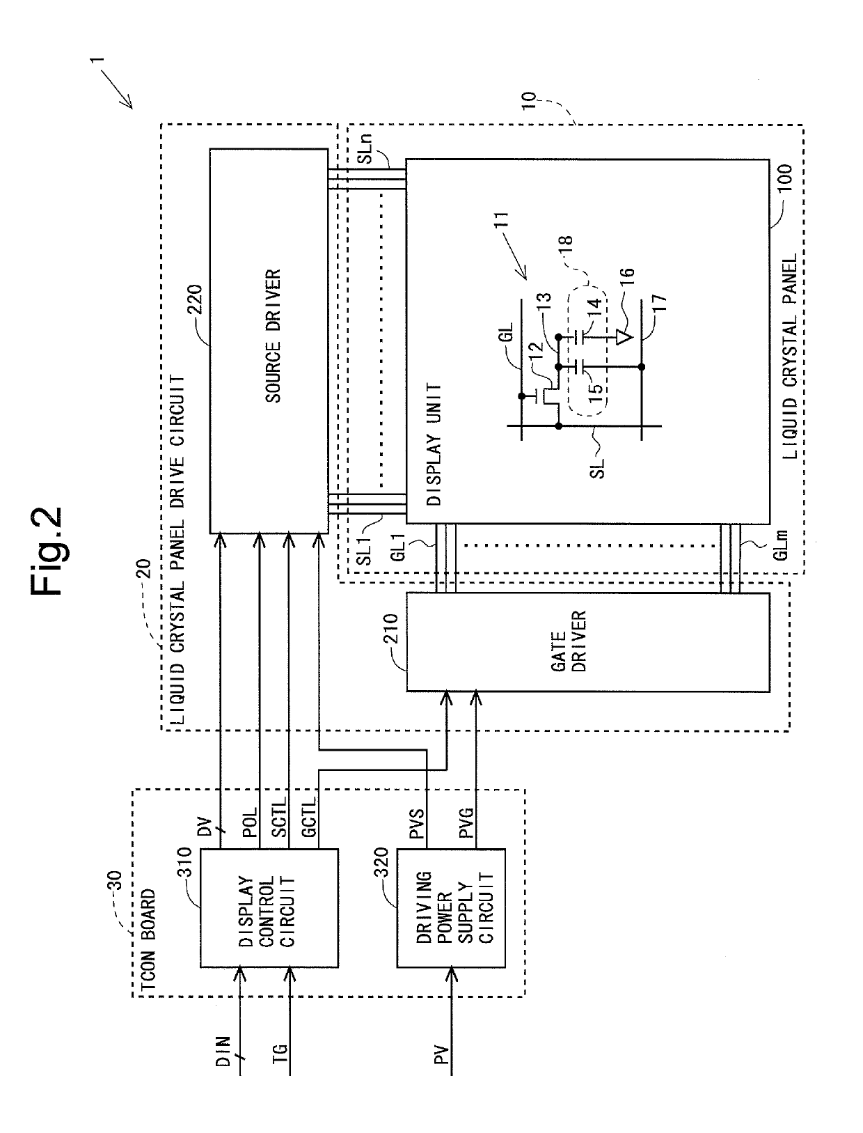
[0062]FIG. 2 is a block diagram illustrating an overall configuration of a liquid crystal display device 1 according to a first embodiment of the present invention. The liquid crystal display device 1 includes: a liquid crystal panel 10 including a display unit 100; a liquid crystal panel drive circuit 20 configured to drive the liquid crystal panel 10; a display control circuit 310 configured to control an operation of the liquid crystal panel drive circuit 20; and a driving power supply circuit 320 configured to supply a power supply voltage to the liquid crystal panel drive circuit 20. The liquid crystal panel drive circuit 20 includes a gate driver 210 and a source driver 220.

[0063]The display control circuit 310 and the driving power supply circuit 320 are mounted on a TCON board 30 in the form of an IC. The liquid crystal panel 10 includes two glass substrates (an array substrate and a color filter substrate). A known method such as a TAB method, a COG...

second embodiment

2. Second Embodiment

[0114]A second embodiment of the present invention will be described. In the following description, points different from the first embodiment will be mainly described, and a description of points similar to the first embodiment will be omitted.

[0115]

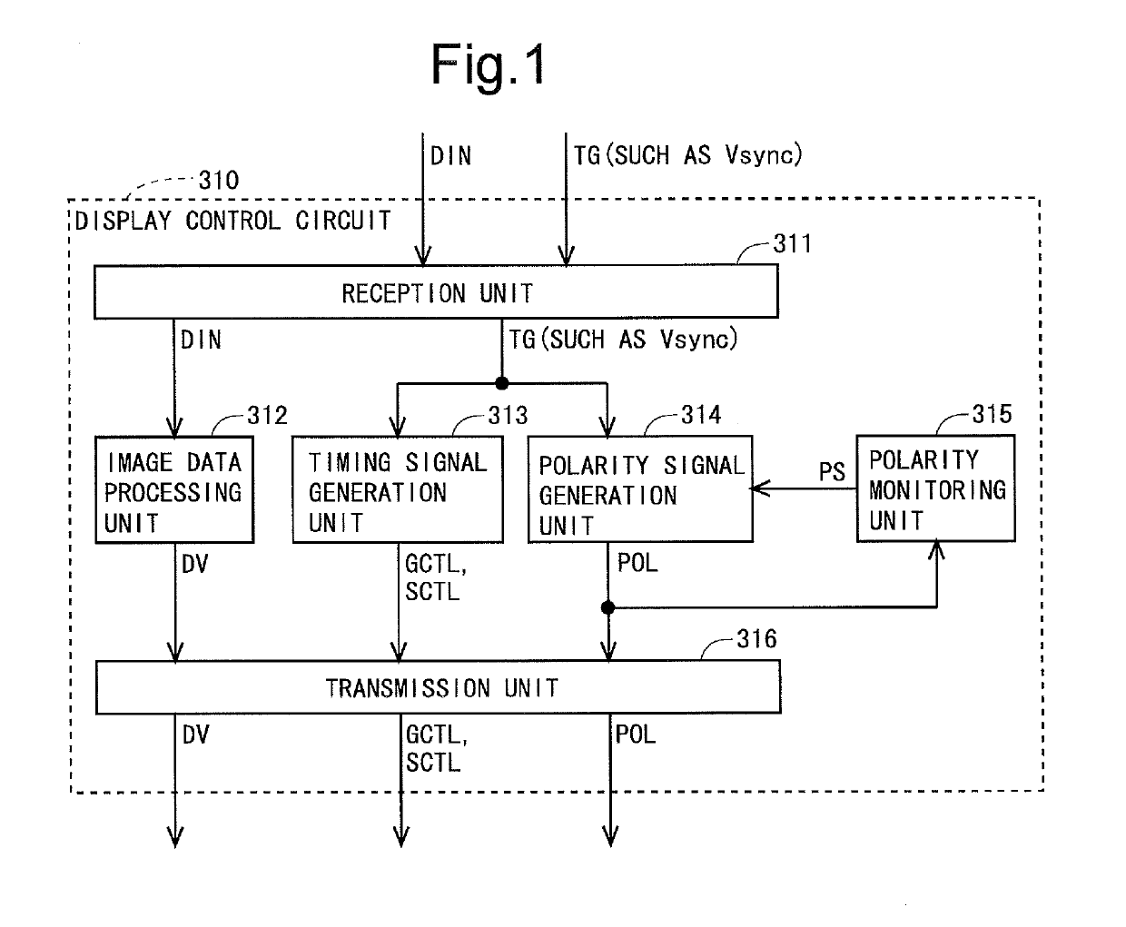
[0116]FIG. 10 is a block diagram illustrating a configuration of a display control circuit 310 according to the present embodiment. The display control circuit 310 includes a reception unit 311, an image data processing unit 312, a timing signal generation unit 313, a polarity signal generation unit 314, a polarity control unit 317, and a transmission unit 316. The reception unit 311, the image data processing unit 312, the timing signal generation unit 313, and the transmission unit 316 operate in the same manner as in the first embodiment.

[0117]The polarity control unit 317 outputs a polarity control signal PCTL that is a signal indicating the polarity of the liquid crystal application voltage and is a signal for c...


PUM


Abstract

In a display control circuit (310) of a liquid crystal display device, there are provided: a polarity monitoring unit (315) configured to monitor a polarity signal (a signal for controlling a polarity of a liquid crystal application voltage) (POL) given to a liquid crystal panel drive circuit; and a polarity signal generation unit (314) configured to generate the polarity signal (POL) such that an increase in a polarity time difference (a difference between a length of a period during which a positive polarity voltage is applied to a liquid crystal and a length of a period during which a negative polarity voltage is applied to the liquid crystal) is suppressed on the basis of a polarity maintenance signal (PS) as a monitoring result produced by the polarity monitoring unit (315).

Description

TECHNICAL FIELD[0001]The present invention relates to a liquid crystal display device, and more specifically, to a liquid crystal display device configured to display an image while changing a frame frequency, and to a method of controlling the same.BACKGROUND ART[0002]Heretofore, a liquid crystal display device has been used for various purposes. The liquid crystal display device is a display device configured to display an image by transmitting / blocking light using properties of liquid crystal that arrangement of molecules changes when the molecules are applied with a voltage. Regarding such a liquid crystal display device, it is known that the liquid crystal deteriorates and screen burn-in occurs when a direct voltage is applied to the liquid crystal for a long time. Therefore, in the liquid crystal display device, AC drive in which a positive polarity voltage and a negative polarity voltage are alternately applied to the liquid crystal is performed. For example, as illustrated i...

Claims


Application Information

Patent Timeline
Patent Type & Authority Applications(United States)
IPC IPC(8): G09G3/36
CPCG09G3/3614G09G3/3696G09G2320/046G09G2310/08G09G2340/0435G09G3/3688G02F1/133G09G3/20G09G3/36
Inventor SASAKI, TAKASHIOZEKI, GOZO
Owner SHARP KK
Why Eureka
Try Eureka