
Fuel cell separators capable of suppressing variation in pressure loss

a technology of pressure loss and separator, which is applied in the field of fuel cells, can solve the problems of undesired damage difficulty in applying the desired tightening load to the electrode unit, and inability to efficiently perform power generation, etc., and achieves the effect of simple structur

Active Publication Date: 2014-08-12
HONDA MOTOR CO LTD
View PDF19 Cites 1 Cited by
  • Summary
  • Abstract
  • Description
  • Claims
  • Application Information

AI Technical Summary

Benefits of technology

The present invention provides a fuel cell with different numbers of flow grooves for the same reactant gas in the gas flow fields without affecting power generation characteristics. This is achieved by maintaining the same length of the flow fields and the same depth of the flow grooves in both fields. The invention suppresses variation in the pressure loss and maintains the same power generation characteristics with a simple structure.

Problems solved by technology

Thus, it is difficult to apply the desired tightening load to the electrode unit 2A.
Consequently, power generation cannot be performed efficiently, and the electrode units 2A, 2B may be damaged undesirably.

Method used


Image

  • Fuel cell separators capable of suppressing variation in pressure loss
  • Fuel cell separators capable of suppressing variation in pressure loss
  • Fuel cell separators capable of suppressing variation in pressure loss

Examples


Embodiment Construction

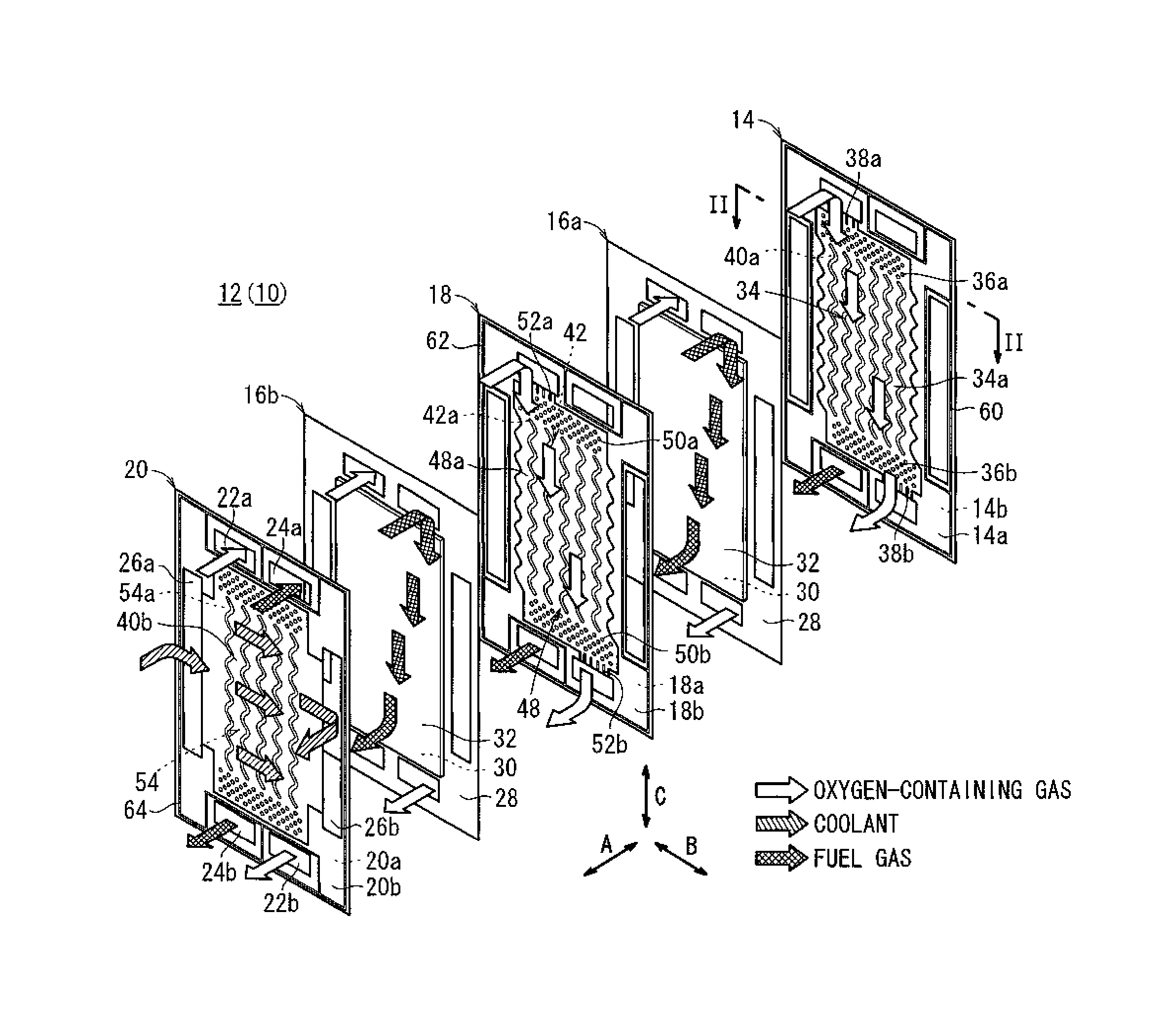
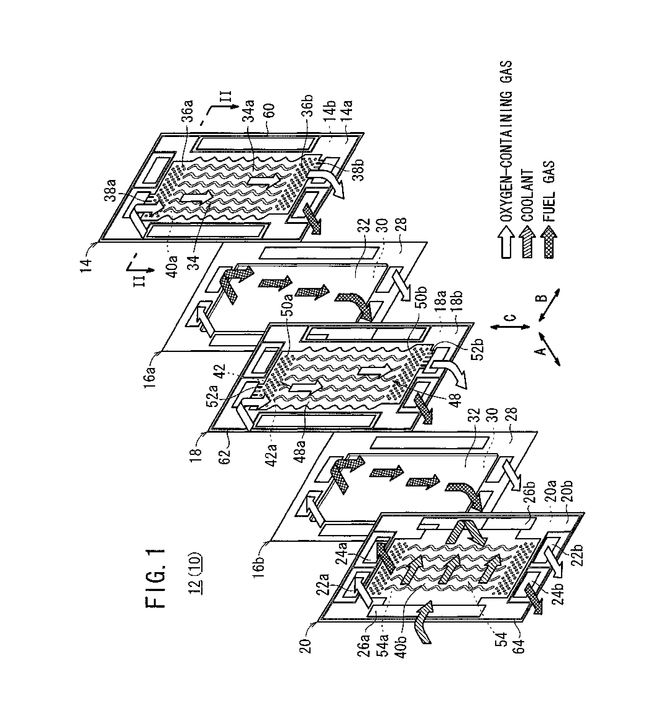
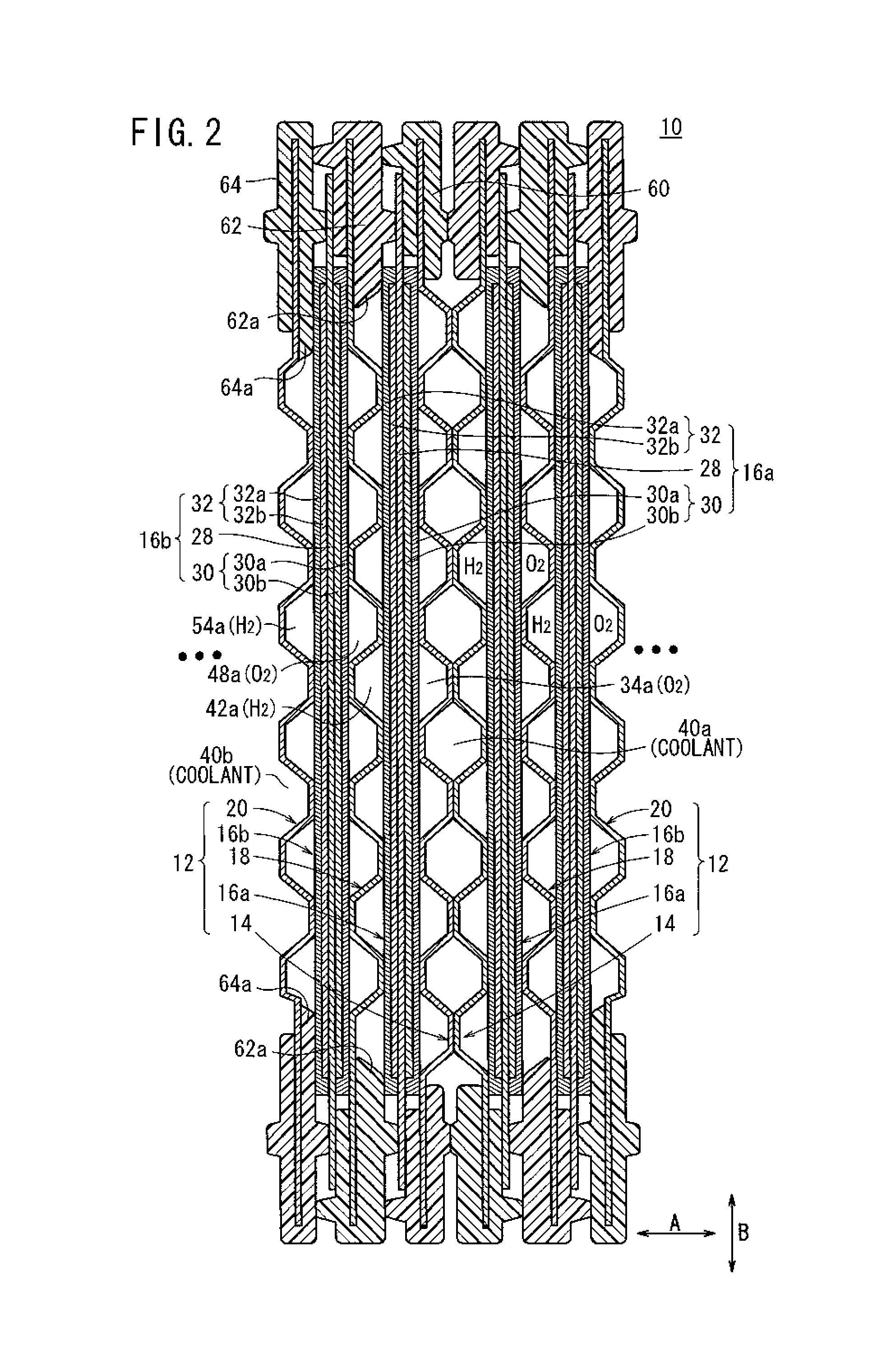
[0027]A fuel cell 10 is formed by reversing a plurality of power generation units 12 with respect to one another, and stacking the power generation units 12 in a horizontal direction indicated by an arrow A (see FIGS. 1 and 2). The power generation unit 12 includes a first metal separator 14, a first membrane electrode assembly (MEA) 16a stacked on the first metal separator 14, a second metal separator 18 stacked on the first membrane electrode assembly (MEA) 16a, a second membrane electrode assembly (MEA) 16b stacked on the second metal separator 18, and a third metal separator 20 stacked on the second membrane electrode assembly (MEA) 16b.

[0028]As shown in FIG. 1, at an upper end of the power generation unit 12 in a longitudinal direction, an oxygen-containing gas supply passage 22a for supplying an oxygen-containing gas and a fuel gas supply passage 24a for supplying a fuel gas such as a hydrogen-containing gas are provided. The oxygen-containing gas supply passage 22a and the f...


PUM

PropertyMeasurementUnit
lengthaaaaaaaaaa
depthaaaaaaaaaa
sizeaaaaaaaaaa

Abstract

A fuel cell according to the present invention includes a power generation unit. The power generation unit is formed by stacking a first metal separator, a first membrane electrode assembly, a second metal separator, a second membrane electrode assembly, and a third metal separator. The number of flow grooves in a first oxygen-containing gas flow field is different from the number of flow grooves in a second oxygen-containing gas flow field. The first oxygen-containing gas flow field and the second oxygen-containing gas flow field have the same length, and the flow grooves in the first oxygen-containing gas flow field and the flow grooves in the second oxygen-containing gas flow field have the same depth.

Description

BACKGROUND OF THE INVENTION[0001]1. Field of the Invention[0002]The present invention relates to a fuel cell having a power generation unit including a first metal separator, a first electrolyte electrode assembly stacked on the first metal separator, a second metal separator stacked on the first electrolyte electrode assembly, a second electrolyte electrode assembly stacked on the second metal separator, and a third metal separator stacked on the second electrolyte electrode assembly.[0003]2. Description of the Related Art[0004]For example, a solid polymer electrolyte fuel cell employs a solid polymer electrolyte membrane. The solid polymer electrolyte membrane is a polymer ion exchange membrane, and interposed between an anode and a cathode to form a membrane electrode assembly (electrolyte electrode assembly). Each of the anode and the cathode includes an electrode catalyst layer and porous carbon. The membrane electrode assembly is sandwiched between a pair of separators (bipola...

Claims


Application Information

Patent Timeline
Patent Type & Authority Patents(United States)
IPC IPC(8): H01M2/38H01M2/40H01M8/04H01M8/24H01M50/77
CPCH01M8/241H01M8/0258Y02E60/50H01M8/2483H01M8/242H01M8/0267H01M8/026
Inventor SUGITA, NARUTOSHIODA, MASARUSAKANO, MASAAKIKAWAGOE, NORIMASAKOSAKA, TAKASHI
Owner HONDA MOTOR CO LTD
Learn More