Friction stir welding method and apparatus for structural steel
- Summary
- Abstract
- Description
- Claims
- Application Information
AI Technical Summary
Benefits of technology
Problems solved by technology
Method used
Image

Examples
examples
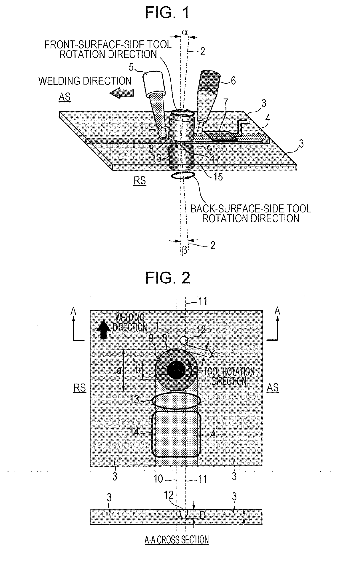
[0149]Friction stir welding was performed using steel sheets (steel sheets 1 together or steel sheets 2 together) having a sheet thickness of 1.60 mm and having the chemical compositions (residual parts other than the compositions in Table 1 are composed of Fe and unavoidable impurities) and the tensile strengths shown in Table 1. The joint abutting faces, which formed a non-angled, so called I-shaped, groove while the surface conditions were similar to those after milling, were subjected to welding while pressing the rotary tool(s) from one surface side or from both the one surface side and the other surface side of steel sheets. The welding conditions for friction stir welding are shown in Table 2 (and Table 5). Conditions L4 and H3 are welding conditions when welding was performed while a rotary tool was pressed from the one surface side of the steel sheets (comparative examples). Conditions L1, L2, L3, H1, and H2 are welding conditions when welding was performed while rotary too...
PUM
| Property | Measurement | Unit |
|---|---|---|
| Fraction | aaaaa | aaaaa |
| Fraction | aaaaa | aaaaa |
| Fraction | aaaaa | aaaaa |
Abstract
Description
Claims
Application Information
 - Generate Ideas
- Intellectual Property
- Life Sciences
- Materials
- Tech Scout
- Unparalleled Data Quality
- Higher Quality Content
- 60% Fewer Hallucinations
Browse by: Latest US Patents, China's latest patents, Technical Efficacy Thesaurus, Application Domain, Technology Topic, Popular Technical Reports.
© 2025 PatSnap. All rights reserved.Legal|Privacy policy|Modern Slavery Act Transparency Statement|Sitemap|About US| Contact US: help@patsnap.com