Gas nozzle for arc welding

A gas nozzle and arc welding technology, applied in arc welding equipment, welding equipment, welding accessories, etc., can solve the problems of hindering the flow of shielding gas, burning the welding torch 21, and reducing welding quality, so as to improve welding quality and welding operation performance, ensure protection, and achieve the effect of welding quality

Inactive Publication Date: 2008-02-06
SUBARU CORP
View PDF4 Cites 3 Cited by
  • Summary
  • Abstract
  • Description
  • Claims
  • Application Information

AI Technical Summary

Problems solved by technology

The spatter S deposited on the gas nozzle 25 may hinder the flow of the shielding gas, deteriorating the protection during welding, causing voids such as pores or pits to be generated at the welding position, and reducing the welding quality.
[0004] In addition, the spatter S will also adhere and accumulate on the surface of the contact tip 24, and connect with the spatter S attached to the gas nozzle 25, so that the contact tip 24 and the gas nozzle 25 are electrically connected through the spatter S, which may cause When the nozzle tip portion 25b of the gas nozzle 25 comes into contact with the workpiece W, a short circuit occurs, sparks are generated, and the welding torch 21 is burned or the workpiece W is damaged.

Method used


Image

  • Gas nozzle for arc welding
  • Gas nozzle for arc welding
  • Gas nozzle for arc welding

Examples


no. 1 Embodiment approach

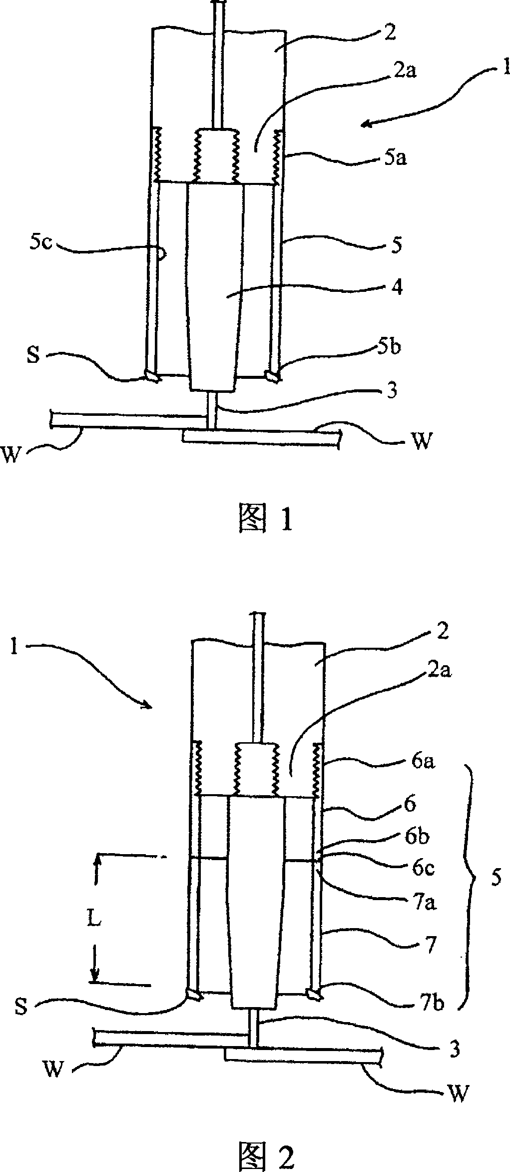
[0033] Fig. 1 is a schematic cross-sectional view of a welding torch equipped with a gas nozzle according to a first embodiment of the present invention.

[0034] In the welding torch 1, a metal contact tip 4 is detachably screwed and fastened to the front end 2a of the welding torch head 2, which is used to supply the welding wire 3 as a consumable electrode, and at the same time, the base of the gas nozzle 5 The end 5a is screwed and fastened to the front end 2a of the torch head 2, and a gas nozzle 5 is detachably installed so as to surround the contact nozzle 4, and the gas nozzle 5 extends from the base end 5a side as a gas jet The nozzle tip 5b on the exit side is formed in a cylindrical shape.

[0035] In addition, the welding wire 3 is used as the electrode on the positive electrode side, and the workpiece W, which is the part to be welded, is used as the electrode on the negative electrode side, while argon and CO are fed into the gas nozzle 5. 2 The inert gas is used as ...

no. 2 Embodiment approach

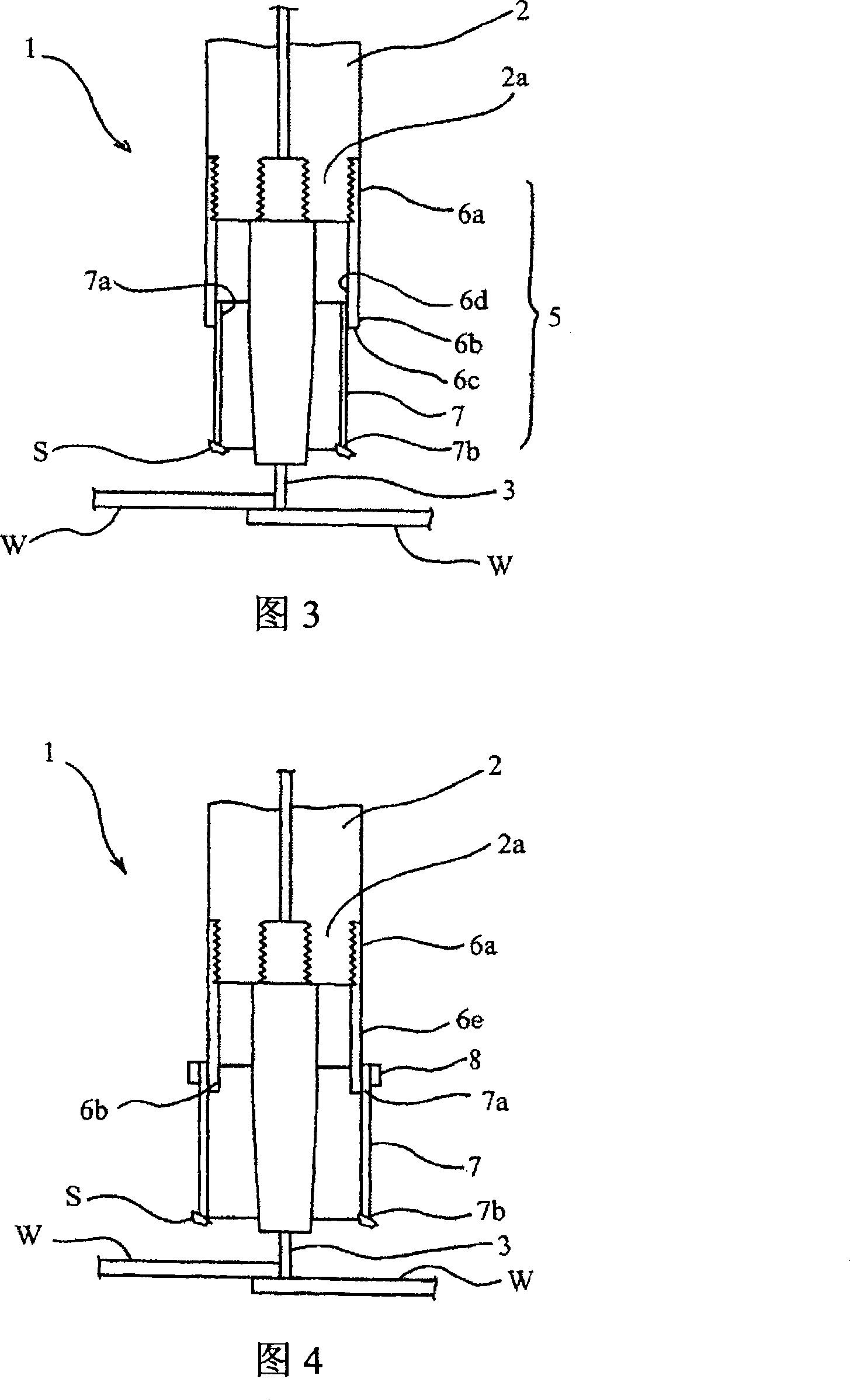
[0042] Fig. 2 is a schematic cross-sectional view of a welding torch equipped with a gas nozzle according to a second embodiment of the present invention.

[0043] In this embodiment, based on the first embodiment, the gas nozzle 5 is made up of the following parts: a cylindrical metal base end nozzle 6 whose base end 6a is detachably screwed and fastened to the welding torch Head 2 on the front end portion 2a; and the front end side nozzle 7, the base end portion 7a of which is detachably bonded to the end surface 6c of the front end portion 6b of the base end side nozzle 6, and the front end side nozzle 7 is made of cardboard The cardboard is a material that is carbonized due to the adhesion of spatter S, and the carbonized part falls off together with the spatter S, and the tip side nozzle 7 extends from the base end 7a side to the tip of the nozzle as the gas ejection side 7b is formed in a cylindrical shape, and since the other structure of the welding torch 1 is the same as ...

no. 3 Embodiment approach

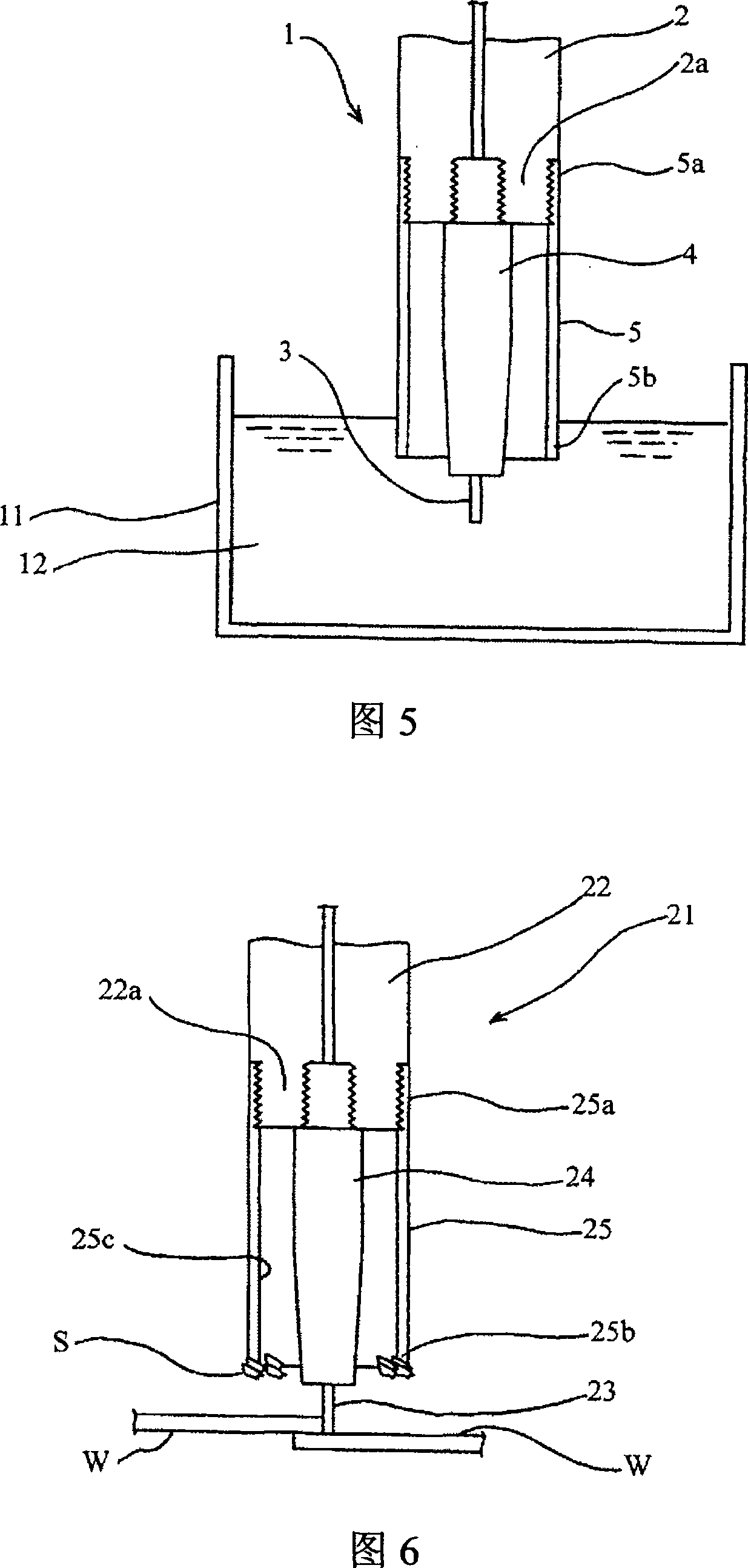
[0046] Fig. 3 is a schematic cross-sectional view of a welding torch equipped with a gas nozzle according to a third embodiment of the present invention.

[0047] In this embodiment, on the basis of the second embodiment, the base end portion 7a of the tip end side nozzle 7 is inserted / detachably bonded to the inner peripheral surface 6d of the tip end portion 6b of the base end side nozzle 6, and the welding torch The other structure of 1 is the same as that of FIG. 2, and a detailed description of the part is omitted by attaching the same reference numerals to the parts corresponding to FIG. 2.

[0048] According to this embodiment, in addition to obtaining the same effect as the second embodiment, compared with the case where the tip side nozzle 7 is bonded to the tip surface 6c of the proximal side nozzle 6 as in the second embodiment, it is possible to use The insertion of the tip nozzle 7 is easier, the replacement operation can be performed smoothly, and maintenance is simp...


PUM

PropertyMeasurementUnit
melting pointaaaaaaaaaa

Abstract

A simple and inexpensive gas nozzle for arc welding capable of reducing adhesion of sputter and enhancing welding quality and welding workability. A gas nozzle (5) so fixed removably to the torch head (2) of a welding torch (1) as to surround a contact chip (4) for feeding a welding wire (W) is formed of a material, e.g., a pasteboard a part of which is carbonized through adhesion of sputter (S) and comes off together with the sputter (S). When the sputter (S) adheres to the gas nozzle (5) during welding, the adhering part is carbonized because of the heat of the sputter (S) and comes off together with the sputter (S). Consequently, adhesion and deposition of the sputter (S) onto the gas nozzle (5) can be reduced infallibly.

Description

Technical field [0001] The present invention relates to a gas nozzle for arc welding which is mounted on, for example, a welding torch of a consumable electrode type arc welding machine. Background technique [0002] For example, in consumable electrode arc welding such as MIG welding, a welding torch 21 as shown in a schematic cross-sectional view in FIG. 6 is used. The welding torch 21 is configured such that a metal contact tip 24 is detachably screwed and fastened to the tip portion 22a of the insulating torch head 22, and the contact tip 24 is used to supply welding wire 23 as a consumable electrode. At the same time, the base end portion 25a of the metal gas nozzle 25 is detachably fastened and screwed so as to surround the contact tip 24. Thus, the welding wire 23 is used as the electrode on the positive electrode side, and the workpiece W, which is the material to be welded, is used as the electrode on the negative electrode side. While inert gas such as argon is fed into...

Claims


Application Information

Patent Timeline
Patent Type & Authority Applications(China)
IPC IPC(8): B23K9/29
CPCB23K9/293B23K9/325B23K9/295B23K9/29
Inventor 千吉良美利
Owner SUBARU CORP
Why Eureka
Try Eureka