Gas nozzle for arc welding
A gas nozzle, arc welding technology, applied in arc welding equipment, welding equipment, welding accessories, etc., can solve the problems of obstructing the flow of shielding gas, reducing welding quality, burning torch 21, etc., to improve welding quality and welding operation. performance, ensure protection, and achieve the effect of welding quality
- Summary
- Abstract
- Description
- Claims
- Application Information
AI Technical Summary
Problems solved by technology
Method used
Image

Examples
no. 1 Embodiment approach
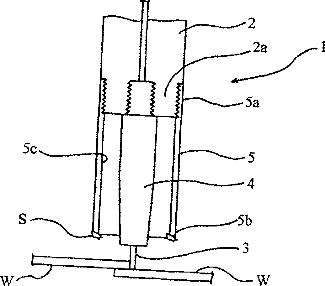
[0033] figure 1 It is a schematic cross-sectional view of a welding torch equipped with a gas nozzle according to the first embodiment of the present invention.
[0034] In this welding torch 1, on the front end 2a of the welding torch head 2, a metal contact tip 4 is detachably screwed and fastened, which is used to supply the welding wire 3 as a consumable electrode, and at the same time, the base of the gas nozzle 5 The end portion 5a is screwed and fastened to the front end portion 2a of the torch head 2, and a gas nozzle 5 is detachably installed in a manner surrounding the contact tip 4. The nozzle tip portion 5b on the outlet side is formed in a cylindrical shape.
[0035] And, with the welding wire 3 as the electrode on the positive side and the workpiece W as the electrode on the negative side, argon gas, CO 2 Using an inert gas as a shielding gas, an arc is generated between the welding wire 3 and the workpiece W, and the welding wire 3 is melted by the heat to we...
no. 2 Embodiment approach
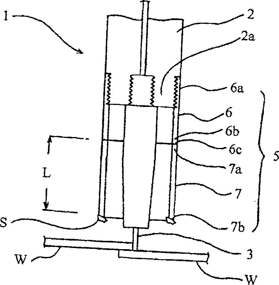
[0042] figure 2 It is a schematic cross-sectional view of a welding torch equipped with a gas nozzle according to a second embodiment of the present invention.
[0043] In this embodiment, on the basis of the first embodiment, the gas nozzle 5 is composed of a cylindrical metal base end side nozzle 6 whose base end 6a is detachably screwed and fastened to the welding torch. On the front end portion 2a of head 2; And front end side nozzle 7, its base end portion 7a is bonded on the end surface 6c of the front end portion 6b of this base end side nozzle 6 freely, and this front end side nozzle 7 is made of cardboard Composition, the cardboard is carbonized due to the attachment of spatter S, and the carbonized part will fall off together with the spatter S, the front end side nozzle 7 is from the base end part 7a side to the nozzle front end part as the gas ejection side 7b is formed in a cylindrical shape, because other structures of the welding torch 1 and figure 1 Since t...
no. 3 Embodiment approach
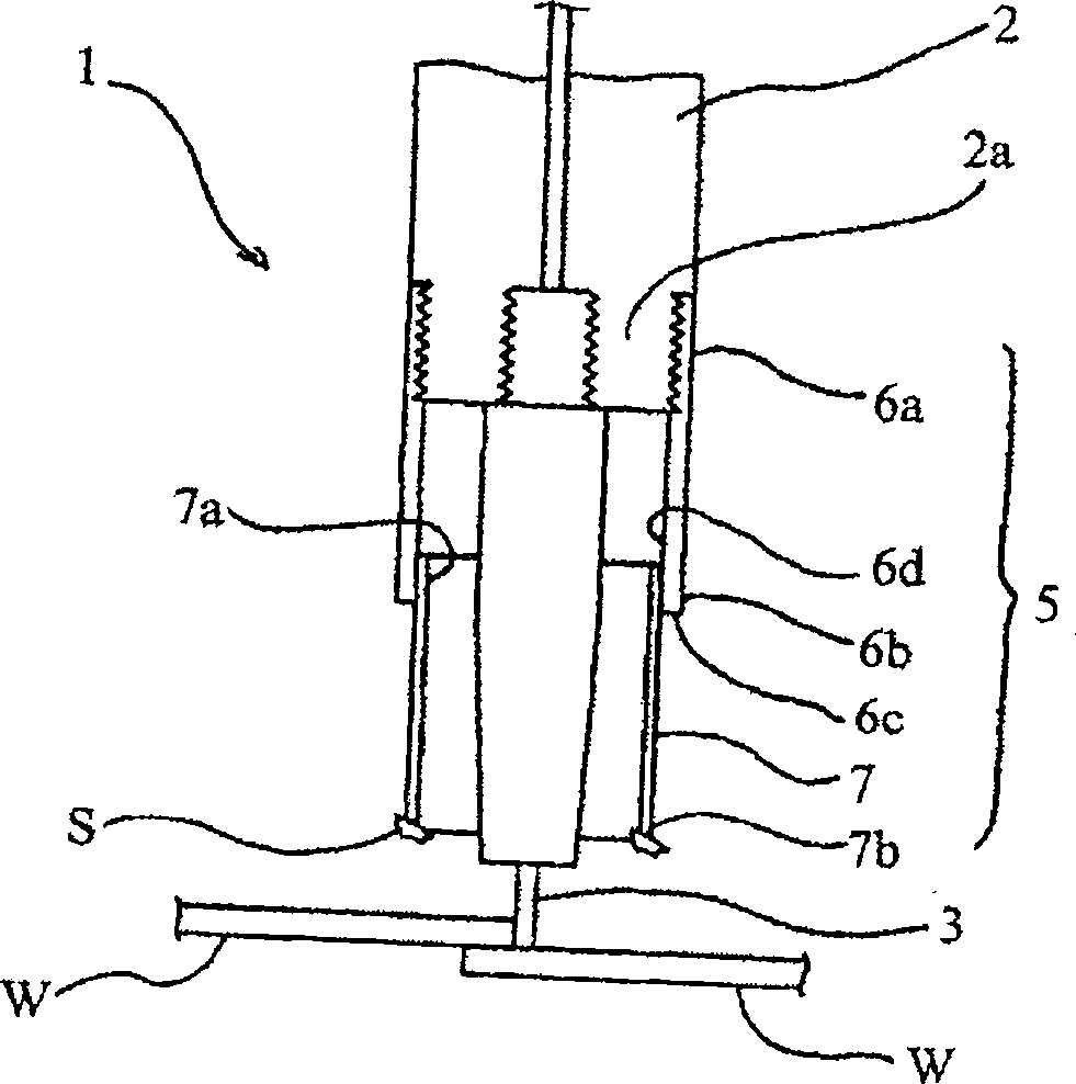
[0046] image 3 It is a schematic cross-sectional view of a welding torch equipped with a gas nozzle according to a third embodiment of the present invention.
[0047] In this embodiment, on the basis of the second embodiment, the base end portion 7a of the front end side nozzle 7 is adhered to the inner peripheral surface 6d of the front end portion 6b of the base end side nozzle 6 in an insertable / detachable manner, and the welding torch 1 other structures with figure 2 same, by pairing with figure 2 Corresponding parts are denoted by the same reference numerals, and a detailed description of the parts is omitted.
[0048] According to this embodiment, in addition to obtaining the same effect as the second embodiment, compared with the case where the distal end side nozzle 7 is bonded to the distal end surface 6c of the proximal end side nozzle 6 as in the second embodiment, it is possible to use Insertion of the tip nozzle 7 becomes easier, and this replacement work ca...
PUM
| Property | Measurement | Unit |
|---|---|---|
| melting point | aaaaa | aaaaa |
Abstract
Description
Claims
Application Information
 - Generate Ideas
- Intellectual Property
- Life Sciences
- Materials
- Tech Scout
- Unparalleled Data Quality
- Higher Quality Content
- 60% Fewer Hallucinations
Browse by: Latest US Patents, China's latest patents, Technical Efficacy Thesaurus, Application Domain, Technology Topic, Popular Technical Reports.
© 2025 PatSnap. All rights reserved.Legal|Privacy policy|Modern Slavery Act Transparency Statement|Sitemap|About US| Contact US: help@patsnap.com