Cycloidal reducer

a cycloidal reducer and reducer technology, applied in the direction of yielding couplings, toothed gearings, gearings, etc., can solve the problems of unfavorable assembly, unfavorable assembly efficiency, and increased assembly time, and achieve the effects of reducing assembly time, extending assembly time, and poor assembly efficiency

Inactive Publication Date: 2019-04-18
HIWIN TECH
View PDF7 Cites 4 Cited by
  • Summary
  • Abstract
  • Description
  • Claims
  • Application Information

AI Technical Summary

Benefits of technology

[0005]In view of the above, this invention is made to improve the prior art by overcoming the problems that the conventional cycloidal reducer has poor assembly efficiency, extended assembly time, being easy to cause damages to the components thereof during assembly, expanded backlash, having dead strokes, poor positioning accuracy, and increased impact noise. Thus, the present invention provides a cycloidal reducer, which generally comprises: a housing, which comprises an axial mounting hole and an internal ring gear formed on an inner circumferential surface of the axial mounting hole; an input bushing, which is mounted in the axial mounting hole of the housing for input of a rotational force; and two speed-reduced output units, which are arranged in the axial mounting hole of the housing, the two speed-reduced output units being arranged in opposite directions of a common axis, each of the speed-reduced output units comprising a cycloidal disc, an output member, a cross Oldham coupling member, and a plurality of rolling elements, the cycloidal disc comprising a mounting hole extending therethrough in an axial direction, an external ring gear formed on an outer circumferential surface thereof, and a plurality of cycloidal disc troughs formed in an end face of the cycloidal disc as recessing in the axial direction, the mounting hole receiving the input bushing to fit therein, the external ring gear being set in engagement with the internal ring gear of the housing, each of the cycloidal disc troughs having sidewalls of which one is formed as an inclined surface, the output member having an end face that comprises a plurality of output member troughs formed therein as recessing in the axial direction, the cross Oldham coupling member comprising a central ring section and four coupling sections extending radially from the central ring section in the form of a cross, each of the coupling sections having sidewalls of which one is formed as an inclined surface, two of the coupling sections of the cross Oldham coupling member being respectively received in the cycloidal disc troughs of the cycloidal disc, the other two of the coupling sections of the cross Oldham coupling member being respectively received in the output member troughs of the output member, the rolling elements being arranged between the inclined surfaces of the cycloidal disc and the inclined surfaces of the cross Oldham coupling member and between the sidewalls of the output member troughs of the output member and the sidewalls of the coupling sections of the cross Oldham coupling member. With such an arrangement, effects of enhancing assembly efficiency, reducing transmission backlash, eliminating dead strokes, improving positioning accuracy, and reducing impact noise can be achieved.
[0006]The present invention also provides a cycloidal reducer, which generally comprises: a housing, which comprises an axial mounting hole and an internal ring gear formed on an inner circumferential surface of the axial mounting hole; an input bushing, which is mounted in the axial mounting hole of the housing for input of a rotational force; and two speed-reduced output units, which are arranged in the axial mounting hole of the housing, the two speed-reduced output units being arranged in opposite directions of a common axis, each of the speed-reduced output units comprising a cycloidal disc, an output member, a cross Oldham coupling member, and a plurality of rolling elements, the cycloidal disc comprising a mounting hole extending therethrough in an axial direction, an external ring gear formed on an outer circumferential surface thereof, and a plurality of cycloidal disc troughs formed in an end face of the cycloidal disc as recessing in the axial direction, the mounting hole receiving the input bushing to fit therein, the external ring gear being set in engagement with the internal ring gear of the housing, the output member having an end face that comprises a plurality of output member troughs formed therein as recessing in the axial direction, each of the output member troughs having sidewalls of which one is formed as an inclined surface, the cross Oldham coupling member comprising a central ring section and four coupling sections extending radially from the central ring section in the form of a cross, each of the coupling sections having sidewalls of which one is formed as an inclined surface, two of the coupling sections of the cross Oldham coupling member being respectively received in the cycloidal disc troughs of the cycloidal disc, the other two of the coupling sections of the cross Oldham coupling member being respectively received in the output member troughs of the output member, the rolling elements being arranged between the sidewalls of the cycloidal disc troughs of the cycloidal disc and the sidewalls of the coupling sections of the cross Oldham coupling member and between the inclined surfaces of the output member and the inclined surfaces of the cross Oldham coupling member. With such an arrangement, effects of enhancing assembly efficiency, reducing transmission backlash, eliminating dead strokes, improving positioning accuracy, and reducing impact noise can be achieved.

Problems solved by technology

This may cause tipping of the rolling elements and re-positioning is necessary for the assembly operation.
This leads to a lower efficiency of assembly and extension of assembly time, and may even cause undesired damages to the rolling elements, the cycloidal disc, the cross Oldham coupling member, and the output member.
This, however, increases the plays between the components and the backlash is expanded, making it easy to generate dead strokes during rotation and drawbacks, such as poor positioning accuracy and increased impact noise, may be caused.

Method used


Image

  • Cycloidal reducer
  • Cycloidal reducer
  • Cycloidal reducer

Examples


Embodiment Construction

[0016]The following descriptions are exemplary embodiments only, and are not intended to limit the scope, applicability or configuration of the invention in any way. Rather, the following description provides a convenient illustration for implementing exemplary embodiments of the invention. Various changes to the described embodiments may be made in the function and arrangement of the elements described without departing from the scope of the invention as set forth in the appended claims.

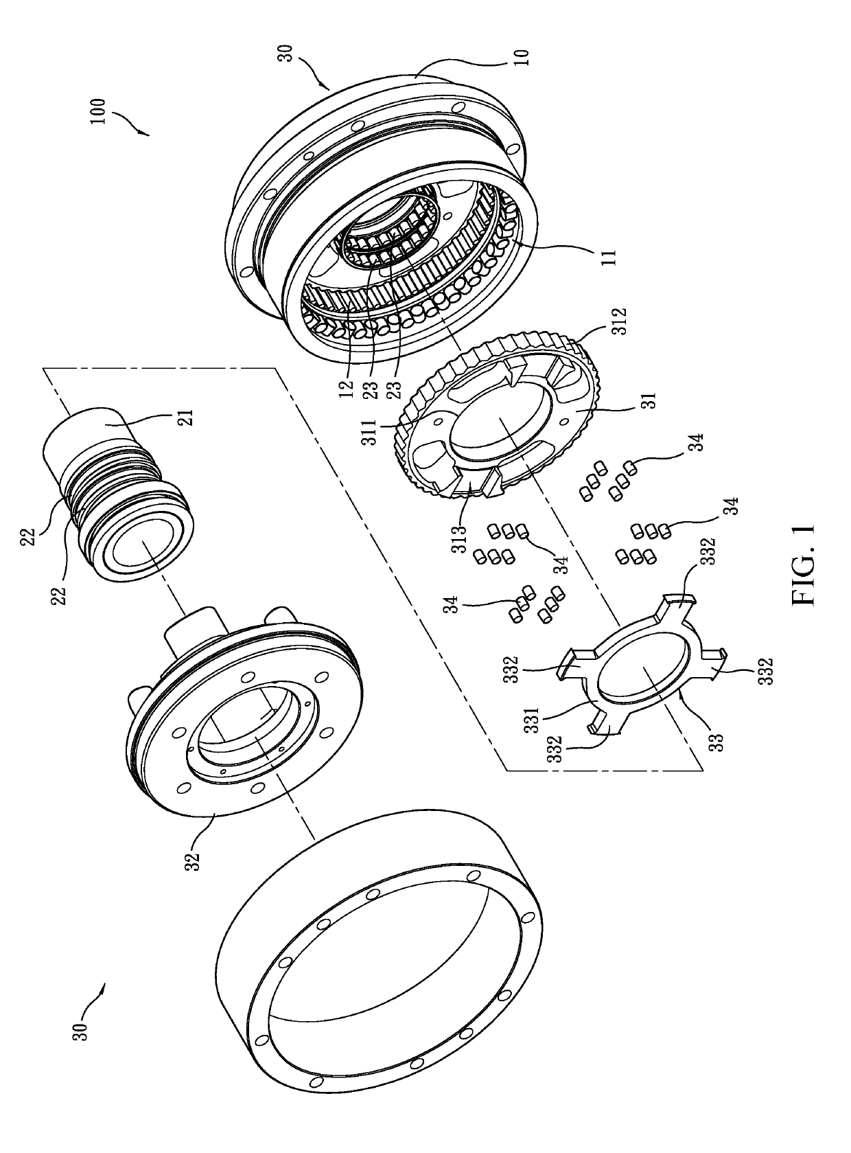
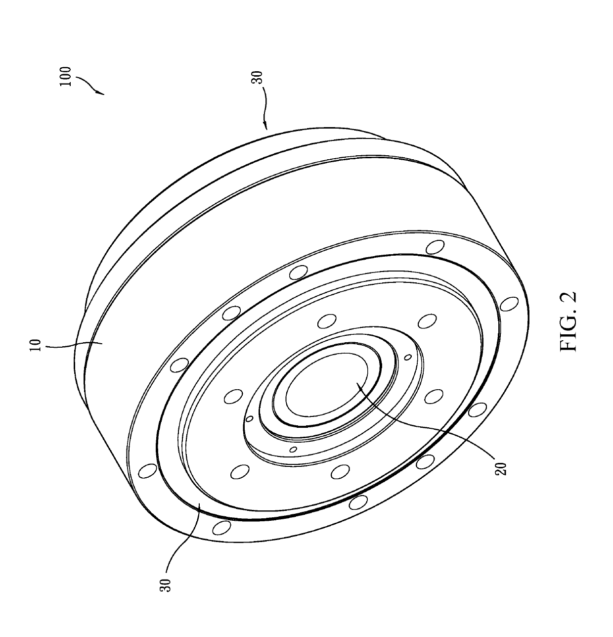
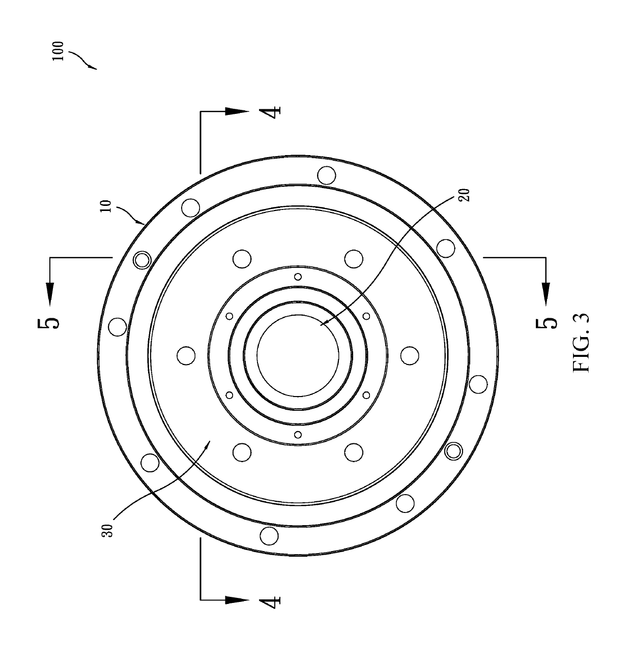
[0017]Referring to FIGS. 1-5, the present invention provides, in a preferred embodiment, a cycloidal reducer 100, which generally comprises a housing 10, an input bushing 20, and two speed-reduced output units 30.

[0018]Referring to FIGS. 1-5, the housing 10 comprises an axial mounting hole 11 and an internal ring gear 12 formed on an inner circumferential surface of the axial mounting hole 11.

[0019]Referring to FIGS. 1-5, the input bushing 20 comprises a bushing 21, two eccentric collars 22 mounted ...


PUM


Abstract

A cycloidal reducer includes a housing, an input bushing mounted in the housing for input of a rotational force, and two speed-reduced output units, each of which includes a cycloidal disc, an output member, a cross Oldham coupling member, and a plurality of rolling elements. The cycloidal disc is mounted to the input bushing and has troughs formed in an end face thereof and each having a sidewall forming an inclined surface. The output member has troughs formed in an end face thereof. The cross Oldham coupling member has coupling sections, each having a sidewall forming an inclined surface. The coupling sections are respectively received in the troughs of the cycloidal disc and the output member. The rolling elements are arranged between the inclined surfaces of the cycloidal disc and the cross Oldham coupling member and between the sidewalls of the output member and the cross Oldham coupling member.

Description

(a) TECHNICAL FIELD OF THE INVENTION[0001]The present invention generally relates to a cycloidal reducer, and more particularly to a cycloidal reducer that is capable of enhanced assembly efficiency and reduction of assembly cost.(b) DESCRIPTION OF THE PRIOR ART[0002]A cycloidal reducer is one of the most common speed reduction mechanisms, in which an eccentric input is transmitted by means of tooth difference to achieve an output of a reduced speed.[0003]The structure of a known cycloidal reducer is that non-coaxial transmission is made between a cycloidal disc and an output member (which is in the form of a flange) by means of a cross Oldham coupling member. Thus, it is necessary to provide rolling elements (such as cylindrical rollers) between the cycloidal disc and the cross Oldham coupling member and between the cross Oldham coupling member and the output member in order to reduce power loss. In other words, the cycloidal disc and the output member are both provided with trough...

Claims


Application Information

Patent Timeline
Patent Type & Authority Applications(United States)
IPC IPC(8): F16H1/32F16H1/28F16D3/04
CPCF16H1/32F16H1/2863F16D3/04F16H57/08F16H2001/326
Inventor WANG, CHENG-LUNGCHENG, HSU-MIN
Owner HIWIN TECH
Why Eureka
Try Eureka