Dual band antenna module

Active Publication Date: 2019-04-18
PEGATRON
View PDF0 Cites 7 Cited by
  • Summary
  • Abstract
  • Description
  • Claims
  • Application Information

AI Technical Summary

Benefits of technology

[0004]The invention provides a dual band antenna module with a good

Problems solved by technology

In antenna designs of the dual band systems, one of the designs uses two single band antennas, but such designs often face the problem of poor signal isolation between the two single band antennas.
The distance between t

Method used


Image

  • Dual band antenna module
  • Dual band antenna module
  • Dual band antenna module

Examples


Embodiment Construction

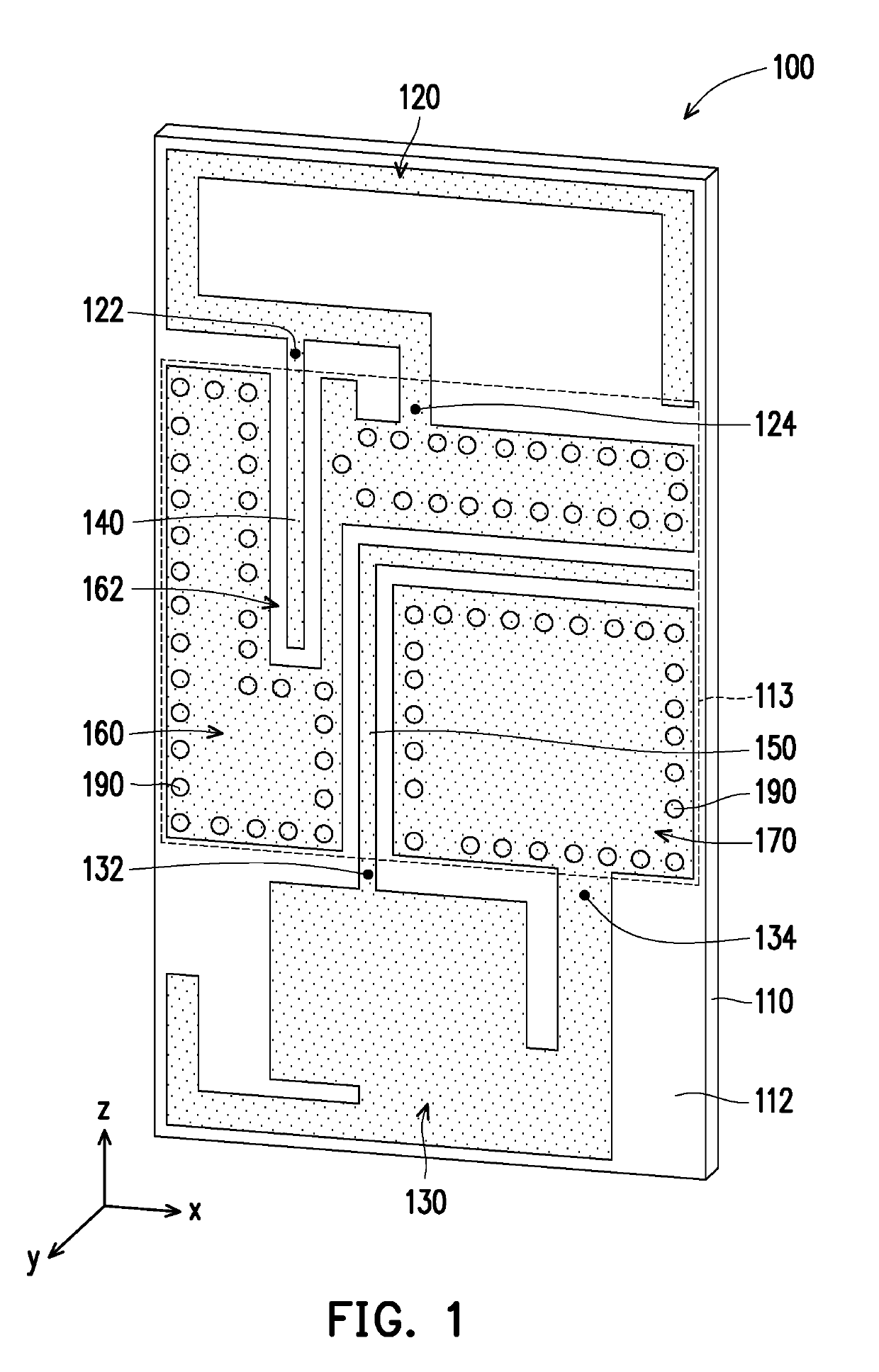
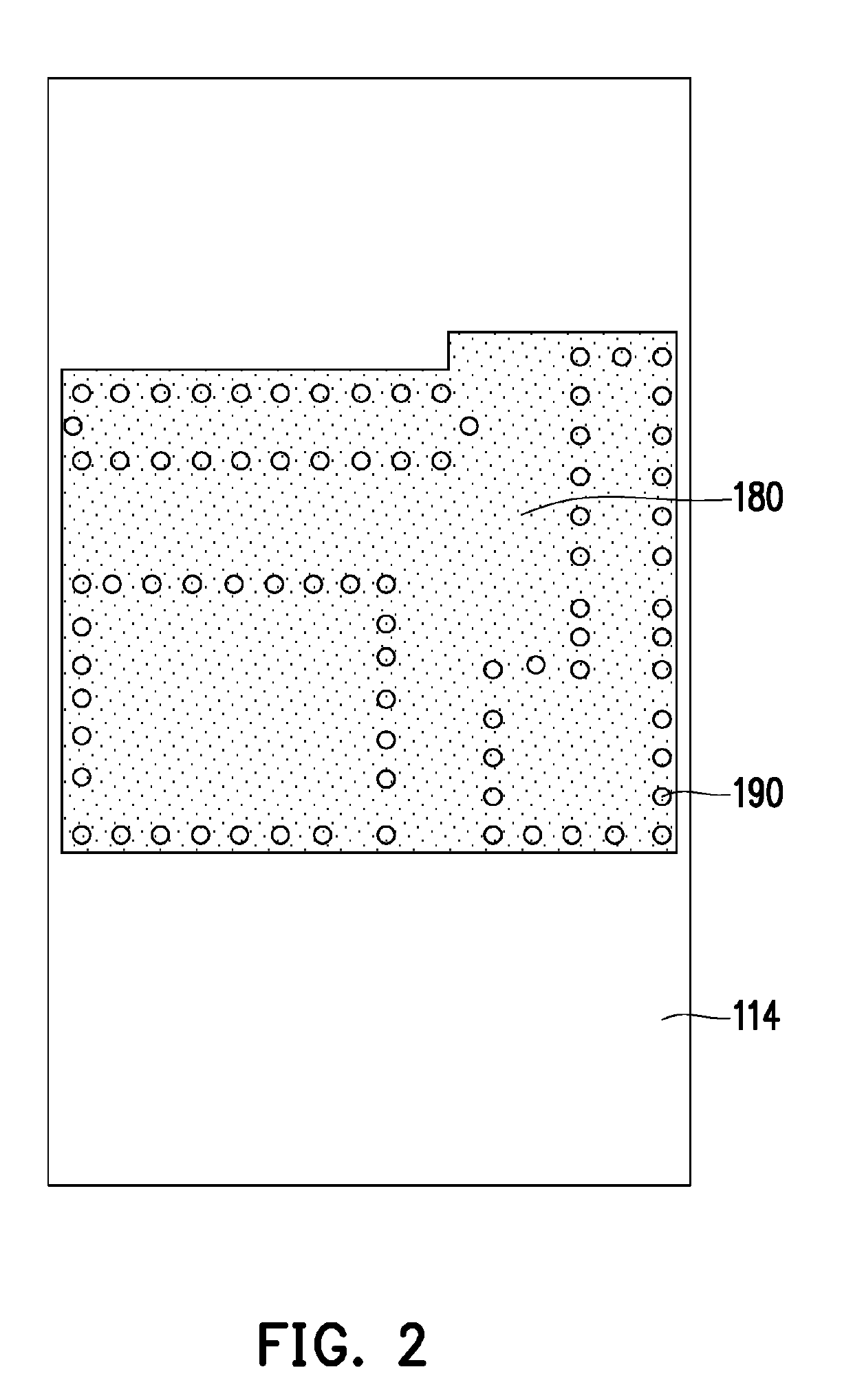
[0021]FIG. 1 is a schematic perspective view of a dual band antenna module according to an exemplary embodiment of the invention. FIG. 2 is a schematic rear view of the dual band antenna module of FIG. 1. Referring to both FIG. 1 and FIG. 2, a dual band antenna module 100 of the exemplary embodiment includes a carrier board 110, a first radiator 120, a second radiator 130, a first filter 140, a second filter 150, a first ground pattern 160, and a second ground pattern 170. The carrier board 110 includes a first surface 112 and a second surface 114 (marked in FIG. 2) opposite each other. As shown in FIG. 1, the first radiator 120, the second radiator 130, the first filter 140 and the second filter 150, the first ground pattern 160 and the second ground pattern 170 are configured on the first surface 112 of the carrier board 110. Certainly, in other exemplary embodiments, the dual band antenna module 100 may omit the carrier board 110 and form directly on a case of an electronic devic...


PUM


Abstract

A dual band antenna module including a first radiator, a second radiator, a first filter and a second filter is provided. The first radiator resonates to generate a first frequency band and includes a first feeding end and a first ground end. The second radiator resonates to generate a second frequency band and includes a second feeding end and a second ground end. The first filter is extended from the first feeding end in a direction away from the first radiator and used for filtering the second frequency band. The second filter is extended from the second feeding end in a direction away from the second radiator and used for filtering the first frequency band.

Description

CROSS-REFERENCE TO RELATED APPLICATION[0001]This application claims the priority benefit of Taiwan application serial no. 106135274, filed on Oct. 16, 2017. The entirety of the above-mentioned patent application is hereby incorporated by reference herein and made a part of this specification.BACKGROUNDTechnology Field[0002]The invention relates to an antenna module, and particularly relates to a dual band antenna module.Description of Related Art[0003]In current wireless transmission systems, dual band systems (for example, including a bandwidth of 2.4G and a bandwidth of 5G, both) are commonly seen. In antenna designs of the dual band systems, one of the designs uses two single band antennas, but such designs often face the problem of poor signal isolation between the two single band antennas. The distance between the two antennas is usually increased to boost the signal isolation, but increasing the distance between the two antennas will increase the overall size of the antenna an...

Claims


Application Information

Patent Timeline
IPC IPC(8): H01Q1/52H01Q5/35H01Q1/48H01Q21/00
CPCH01Q1/523H01Q5/35H01Q1/48H01Q21/0025H01Q5/50H01Q1/36H01Q1/38H01Q1/50H01Q1/52H01Q1/521H01Q9/40H01Q9/42H01Q21/28H01Q5/40H01P1/203H01Q21/30H01Q5/335H01Q1/2291H01Q5/30H01Q9/04
Inventor HUANG, KE-CHINHUANG, JUNG-YIYANG, HUI-AN
Owner PEGATRON
Why Eureka
Try Eureka