Signal processing arrangement, sensor arrangement and signal processing method

Active Publication Date: 2019-04-18
AMS AG
View PDF0 Cites 1 Cited by
  • Summary
  • Abstract
  • Description
  • Claims
  • Application Information

AI Technical Summary

Benefits of technology

[0005]The present disclosure provides an improved signal processing concep

Problems solved by technology

Due to the strict noise requirements and usually small sensor capacitances, a conversion of the signal into a charge domain or current

Method used


Image

  • Signal processing arrangement, sensor arrangement and signal processing method
  • Signal processing arrangement, sensor arrangement and signal processing method
  • Signal processing arrangement, sensor arrangement and signal processing method

Examples


Example

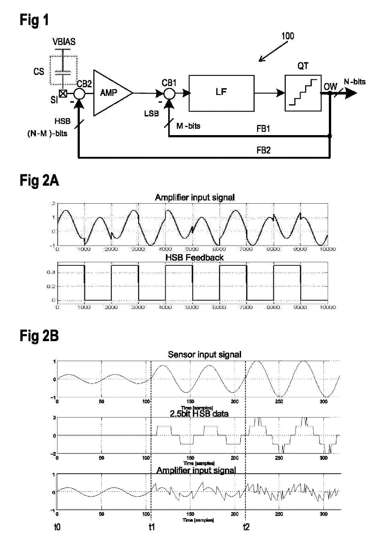
[0043]FIG. 1 shows an example implementation of a sensor arrangement with a signal processing arrangement 100 and a capacitive sensor CS connected to a signal input SI of the signal processing arrangement 100. As a non-limiting example, the capacitive sensor CS may be implemented as a capacitive MEMS sensor. Examples of such MEMS sensor are MEMS microphones or MEMS pressure sensors, biosensors or others. In typical implementations, the capacitive sensor CS is connected between a bias voltage connection VBIAS and a signal input SI, which forms the input of the signal processing arrangement 100.

[0044]The signal input SI is coupled to an input of an amplifier circuit AMP via a combiner CB2. An output of the amplifier circuit AMP is coupled to a loop filter LF via a further combiner CB1. An output of the loop filter LF is connected to a quantizer QT, whose output forms a signal output of the signal processing arrangement 100. The quantizer QT particularly provides a multi-bit output wor...


PUM


Abstract

A signal processing arrangement has a signal input for connecting a capacitive sensor. An amplifier circuit is coupled between the signal input and a feedback point. A loop filter is coupled downstream to the feedback point. A quantizer is connected downstream to the loop filter and provides a multi-bit output word. The multi-bit output word consists of one or more higher significance bits and one or more lower significance bits. A first feedback path is coupled between a quantizer and the feedback point for providing a first feedback signal to the feedback point being representative of the one or more lower significance bits. A second feedback path is coupled to the quantizer for providing a second feedback signal to the signal input being representative of the one or more higher significance bits.

Description

BACKGROUND OF THE INVENTION[0001]The present disclosure relates to a signal processing arrangement, to a sensor arrangement with such signal processing arrangement and to a signal processing method, each processing a signal from a capacitive sensor.[0002]Sensors with capacitive properties are widely used. For example, many micro electro mechanical systems, MEMS, sensors, like MEMS microphones, have a varying capacitance depending on the value to be sensed.[0003]MEMS microphones are an example of a capacitive sensor application where a very high input dynamic range needs to be supported. The signal of the capacitive sensor may have peak values at the input that might even exceed the supply rails of an associated signal processing circuit. For example, such a signal may need to be compressed to fit within the signal swing given a limited supply voltage of a first amplifier of the signal processing circuit. Due to the strict noise requirements and usually small sensor capacitances, a c...

Claims


Application Information

Patent Timeline
IPC IPC(8): H03M3/00H03M1/12H03M1/68
CPCH03M3/49H03M1/1295H03M1/68H03M3/464
Inventor CHRISTEN, THOMASSTEELE, COLINFROEHLICH, THOMAS
Owner AMS AG
Why Eureka
Try Eureka